Sign In
Upload
Download
Table of Contents
Contents
Add to my manuals
Delete from my manuals
Share
URL of this page:
HTML Link:
Bookmark this page
Add
Manual will be automatically added to "My Manuals"
Print this page
×
Bookmark added
×
Added to my manuals
Manuals
Brands
Varta Manuals
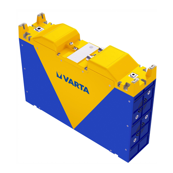
Battery Pack
EASY BLADE
Technical handbook
Varta EASY BLADE Technical Handbook
Hide thumbs
1
Table Of Contents
2
3
4
5
6
7
8
9
10
11
12
13
14
15
16
17
18
19
20
21
22
23
24
25
26
27
28
29
30
31
32
33
page
of
33
Go
/
33
Contents
Table of Contents
Bookmarks
Table of Contents
Table of Contents
General Safety Signs
1 Caution/Warning Statements
General Hazard Sources
Safety Overview on Battery Management System (BMS)
Certification
2 Contact Details
3 Introduction of ASB
Definitions and Standards
General Design and Application Criteria
Features
4 Reference Table: Easy Blade
5 Reference Table: Easy Block
6 Description of the Battery
Easy Blade
Easy Block
Included in the Box
Additional Systems Requirements
Push Button
LED Indications
7 Setup a System
Mechanical Connection
Electrical Connection
Configuration of a System
Start the Battery/System
Shut-Down
8 CAN Communication
9 Easy Blade - Cooling Concept
10 Charging
11 Error
12 The CAN Protocol
Communication Within the Battery System
Communication Sent by the Battery Master (for Application)
Communication Sent by the Battery Master (for Charger)
13 Faqs
Charger
CAN-Communication
Tpdo/Sdo
Parallel Connection
Safety / Life Time
Mechanical
General
Advertisement
Quick Links
1
Led Indications
2
Electrical Connection
3
Can Communication
4
10 Charging
Download this manual
1
Table of
Contents
Previous
Page
Next
Page
1
2
3
4
5
Advertisement
Table of Contents
Need help?
Do you have a question about the EASY BLADE and is the answer not in the manual?
Ask a question
Questions and answers
Related Manuals for Varta EASY BLADE
Camera Accessories Varta Easy Blade 24 V Technical Handbook
(23 pages)
Battery Pack Varta EASY BLOCK Technical Handbook
(33 pages)
Battery Pack Varta VP500 User Manual
Mobile power station (28 pages)
Battery Pack Varta 57982 Quick Start Manual
(2 pages)
This manual is also suitable for:
Easy block
56654 799 098
56654 799 097
56650 764 099
56650 764 098
Easy blade 24 v
...
Show all
Easy blade 48 v
Easy block 24 v
Easy block 48 v
Table of Contents
Print
Rename the bookmark
Delete bookmark?
Delete from my manuals?
Login
Sign In
OR
Sign in with Facebook
Sign in with Google
Upload manual
Upload from disk
Upload from URL


Need help?
Do you have a question about the EASY BLADE and is the answer not in the manual?
Questions and answers