Table of Contents
Advertisement
Advertisement
Table of Contents

Related Manuals for MUSTOOL MT8208


Summary of Contents for MUSTOOL MT8208
- Page 1 Scope Meter User’s Manual...
-
Page 3: Table Of Contents
Preface Dear users, Thank you for purchasing this digital oscilloscope multimeter. We believe its innovative function combination and humanized design will bring great convenience to your site tests. Before use, please carefully read this manual, especial the part of "Safety Instructions". Please also keep this manual property for future reference. Contents SAFETY INSTRUCTIONS..............................1 INTRODUCTION OF INSTRUMENT........................... - Page 4 Amplitude adjustment............................... 9 Trigger control.................................10 Trigger level adjustment............................10 About trigger mode..............................11 About automatic waveform capture........................11 Reminder of scanning status........................... 12 Single scan trigger operation..........................12 Holding of signal waveform........................... 13 Storage and reading of waveform of signals......................13 THE OPERATION OF MULTIMETER........................15 Enter multimeter mode............................
- Page 5 Continuity test................................. 24 Capacitor measurement............................24 10mF capacitor measurement..........................25 The holding of measurement data...........................26 Measurement data storage and reading........................26 TECHNICAL PARAMETERS AND COMPLETE SETS OF INSTRUMENTS............28 General features..............................28 Oscilloscope characteristics............................ 28 Multimeter features..............................29 Display symbols and icons............................30 Complete sets and options of the instrument......................31 DAILY MAINTENANCE AND TROUBLESHOOTING....................32...
-
Page 6: Safety Instructions
Safety Instructions This digital oscilloscope multi-meter is designed in conformity with safety specifications of IEC1010-1. Second category of overvoltage measurement: CAT III - 1000V; pollution protection level: Level 1. 1. Before use, please check the machine shell first to check if there are cracked or any required plastic part is missing. Do not use instrument with broken shell. - Page 7 4. When changing measuring function, please make sure the probe of test leads is taken away from the test point before plugging in/out the plug of test leads and before switching on/off the device; 5. Pay attention to the safety warning signal displayed on the instrument: When the measured voltage exceeds the "safety voltage"...
- Page 8 Safety signs Caution, danger! This sign appears near other signs or socket terminals to remind users that the instruction of the manual must be followed during operation, so as to prevent damage to the instrument/personal injury. Caution, electricity shock! This sign appears near one or more terminals to indicate that there may be hazard voltage in the terminal(s) during use.
-
Page 9: Introduction Of Instrument
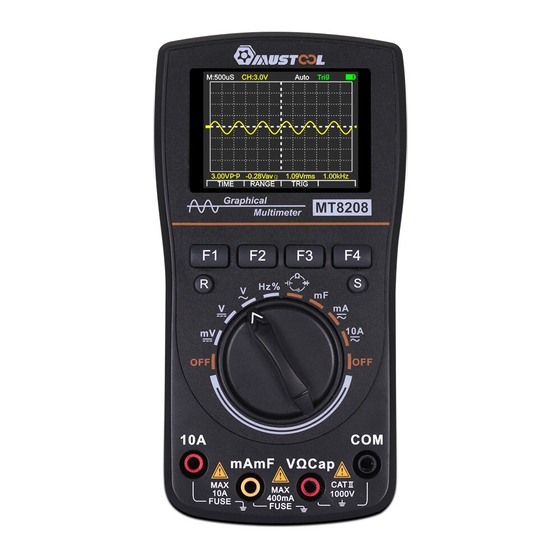
Introduction of Instrument Main features ◆2.5Msps high-speed sampling, 1MHz analog bandwidth(Only for oscilloscopes with ACV), 4000 count digital multimeter. ◆One-click visual wave, there are three waveform scanning modes: automatic/conventional/single. ◆Save function for data and waveform in the measurement; a total of 100 sets of data and 10 waveform can be saved. -
Page 10: Button Functions
Button functions BUTTONS Name Function The actual function varies with the measuring range F1 ~ F4 and work mode. The option menu displayed on the LCD serves as the prompt for action. Multimeter status Manual range Oscilloscope state Automatic capture Data lock and save Instrument switch DC millivolt voltage... -
Page 11: Basic Operation
Basic operation Power on and off Rotate the rotary knob to desired measurement gear and the power is connected to the instrument; rotate the rotary knob to OFF position to turn off the power. • Be sure to move the test probe away from the test point before shutting down. Attention •... -
Page 12: Oscilloscope Operation
Oscilloscope operation Enter oscilloscope mode In multimeter mode (DMM) mode voltage, current range, press the "R" key for 2 seconds to enter the oscilloscope (OSC) mode.In oscilloscope (OSC) mode. Press the "R" key for 2 seconds to enter the multimeter mode (DMM) mode. -
Page 13: Function Buttons And Main Option Menu
Function buttons and main option menu The function buttons of F1~F4 are located at the lower of the LCD screen. With the option menu on the screen, these buttons will enable users to realize several functions. Some functions are provided with sub-option menu for further operations. -
Page 14: Amplitude Adjustment
• When measuring a signal whose frequency is unknown, user has to try to collect the waveform from the fastest time base and then gradually select the slower time base until the signal can be Instructions! displayed correctly. Otherwise, due to "aliasing effect", waveform may fail to correctly reflect the actual situation of the signal. -
Page 15: Trigger Control
Trigger control In the main menu of the oscilloscope mode, press the F3 key (TRIG) to enter the trigger control sub-menu: Back Trigger edge Trigger Mode Trigger level EXIT MODE LEVEL 1. Press the F1 key (EXIT) to exit the trigger control sub-menu and return to the main menu. 2. -
Page 16: About Trigger Mode
About trigger mode Auto : Even if no trigger condition is detected, the oscilloscope can still acquire waveforms. If there is no trigger condition, after the oscilloscope waits for a certain period of time, it will trigger itself and start collecting data. Since there is no correct trigger, the waveform displayed by the oscilloscope scrolls on the screen because it cannot be synchronized. -
Page 17: Reminder Of Scanning Status
Reminder of scanning status Auto In automatic mode, waveforms can be acquired without triggering conditions. wait Wait for the trigger condition. Trig The trigger condition has been detected. Stop Keep locked Single scan trigger operation The steps for single-triggered data collection are as follows: 1. -
Page 18: Holding Of Signal Waveform
Holding of signal waveform When collection of data is continuing, the waveform of signals will be constantly refreshed. When the data collection is stopped, the display content will be held. The main purpose of holding waveform is to hold the current data or waveform, so as to make close observation easier. - Page 19 1. Press the "S" key to keep the current waveform. 2. Press the "S" key and stay for 2 seconds to enter the database, press the F1 key (◄) / F2 key (►) to select the storage location, press the F4 key (SAVE) to save the current waveform. 3.
-
Page 20: The Operation Of Multimeter
The operation of multimeter Enter multimeter mode Turn on the default multimeter mode (DMM) mode, or press the "R" key for a long time to switch modes. • Please read, understand and follow the safety rules and operating methods indicated in the following. Warning! •... -
Page 21: Switching Measurement Function
Switching measurement function Rotate rotary button for selection of test function. The switching of measurement function follows the following circulation order: DCmV/DCV/ACV/HZ/%/Resistance/Diode/Continuity/mF/mA(AC/DC)/10A(AC/DC). For multi-function gear, press the F3 key (SEL) to switch functions. Selection of manual/automatic measuring range The initial state after powering on or switching the measurement function is auto range. For most applications, this is the most convenient measurement method. -
Page 22: Relative Value Measuring Mode
Relative value measuring mode Relative value mode is a measuring mode which displays the difference between the actual measurement value and the reference value. 1. Press F1 key (REL) and the current displayed measurement value will be saved as the reference value. 2. - Page 23 The menu functions of peak hold mode are as follows: Exit the peak value holding Run measurement Stop measurement Reset peak value EXIT STOP REST a. Press the F1 key (EXIT) to exit the peak hold mode. b. Press the F2 key (RUN) to perform peak hold measurement. c.
-
Page 24: Ac And Dc Voltage Measurement
AC and DC voltage measurement When the measured voltage exceeds the "safety voltage" (24V ), the warning information " " Instructions! will be displayed to remind users of "safety". To avoid damage to the instrument, never apply 700V AC or 1000V DC voltage on the Warning! measuring end for more than 10 seconds. -
Page 25: Ac And Dc Current (400Ma,10A)Measurement
AC and DC current (400mA,10A)measurement • To avoid electricity shock, never perform current measurement for circuit with a voltage of 250V or higher. warning • When measuring large current with 10A gear, the measurement duration in every 15 minutes shall not exceed 30 seconds. -
Page 26: Frequency Counting And Measurement Of Duty Ratio
Frequency counting and measurement of duty ratio 1. Insert the banana plug of the black test lead into the negative "COM" socket, and the red plug into the positive "VΩCap" socket as required for measurement. 2. Rotate the knob to select the " "... -
Page 27: Resistance Measurement
Resistance measurement To avoid electric shock, when measuring resistance, please cut off the power supply first of the Warning! device under test (remove the battery/unplug the power cord) and discharge the capacitor in the power supply. 1. Insert the banana plug on the black test lead wire into the negative "COM" socket; the banana plug on the red test lead wire into the positive "VΩCap"... -
Page 28: Diode Detection
Diode detection Warning! To avoid electric shock, the diodes carrying voltage must not be tested. 1. Insert the banana plug on the black test lead wire into the negative "COM" socket; the banana plug on the red test lead wire into the positive "VΩCap" socket. 2. -
Page 29: Continuity Test
Continuity test In order to avoid electric shock, the continuity test must not be carried out on the line carrying Warning! voltage. 1. Insert the banana plug on the black test lead wire into the negative "COM" socket; the banana plug on the red test lead wire into the positive "VΩCap"... -
Page 30: 10Mf Capacitor Measurement
10mF capacitance measurement 1. Insert the banana plug on the black test lead wire into the negative "COM" socket; the banana plug on the red test lead wire into the positive "mAmF" socket. 2. Rotate the knob to select the " "... -
Page 31: The Holding Of Measurement Data
The holding of measurement data Press the data hold key "S", the reading being displayed will be held down, at this time the LCD screen will display the data hold icon "STOP". Press the "S" key again to resume normal operation. 1. - Page 32 3. If data is stored at a certain location, the value and unit of this data will be listed. Press the "S" key again and stay for 2 seconds to exit the database function. The menu operation of the database is as follows: Choose where to record Select adjacent page Record deletion Save the data that has been kept ▼...
-
Page 33: Technical Parameters And Complete Sets Of Instruments
Technical parameters and complete sets of instruments General features Display 240 × 320 Color screen Observation area 49.0 mm x 36.72 mm Backlight Constantly on Input resistance About 10MΩ Battery AA batteries*3 Auto shutdown 15 minutes or disabled Working current About 65mA Sleep current About 35uA... -
Page 34: Multimeter Features
Multimeter features The uncertainty of all ranges is expressed as: ± (a% reading + word count). The correction period is one year. The environmental conditions with guaranteed uncertainty are: 23°C±5°C, <75%RH. Function Range Resolution Uncertainty 400mV 0.1mV DC voltage (1.5%rdg + 10dgt)/1000V 4V/40V/400V/1000V 1mV/10mV/100mV/1V 50Hz ~1kHz... -
Page 35: Display Symbols And Icons
51.2nF/512nF/5.12μF/51.2μF 10pF/100pF/1nF/10nF (3.0%rdg + 10dgt) Capacitance 100μF 100nF 10mF 1μF (5.0%rdg + 15dgt) Frequency 5Hz~5MHz Amplitude≧2Vp-p (1.0%rdg + 5dgt) (more than 5M for reference only) Diode / continuity test Open circuit voltage is about 1.5 V; judgment resistance: about 50Ω Fuse specifications 500mA/250V ,10A/250V Display symbols and icons... -
Page 36: Complete Sets And Options Of The Instrument
Reference end of measurement Average value ERASE Erase record LEVEL Trigger level SAVE Save current signal to memory RESET Trigger level to zero Normal Normal trigger means Single Single-time waveform Auto Automatic trigger mode Trig Scan trigger Wait Ready to wait for trigger Stop Hold waveform TIME... -
Page 37: Daily Maintenance And Troubleshooting
Daily maintenance and troubleshooting Keep the instrument dry If the instrument is wet, please wipe it until it’s dry. If you are not sure whether it’s dry, please do not use it . Please store and use the instrument in ambient temperature Extreme ambient temperature will reduce the service life of electric components, deform plastic parts or even cause non-availability for use of the instrument. - Page 38 Repair and maintenance of the instrument 1. This is a precision instrument. Without the authorization of the products center of the company, please do not alter any circuit, replace any component or perform any calibration or repair of the product. 2.
- Page 39 Replacement battery When the LCD display shows a red " " prompt, the battery should be replaced in time (battery specification: AA1.5Vx3), otherwise the measurement accuracy may be affected. Steps: 1. Remove the test leads and set the position to "OFF"; open the battery cover and take out the old battery (take the middle battery first).
Need help?
Do you have a question about the MT8208 and is the answer not in the manual?
Questions and answers