Sign In
Upload
Download
Table of Contents
Contents
Add to my manuals
Delete from my manuals
Share
URL of this page:
HTML Link:
Bookmark this page
Add
Manual will be automatically added to "My Manuals"
Print this page
×
Bookmark added
×
Added to my manuals
Manuals
Brands
Midea Manuals
Air Conditioner
MI2-28Q4DHN1
Installation and operation manual
Midea MI2-28Q4DHN1 Installation And Operation Manual
Four-way cassette the 2nd generation dc vrf indoor unit
Hide thumbs
1
2
Table Of Contents
3
4
5
6
7
8
9
10
11
12
13
14
15
16
17
18
19
20
21
22
23
24
25
page
of
25
Go
/
25
Contents
Table of Contents
Troubleshooting
Bookmarks
Table of Contents
Table of Contents
Installation Manual
Accessories
Before Installation
Choosing an Installation Site
Indoor Unit Installation
Refrigerant Piping Installation
Water Discharge Piping Installation
Electrical Wiring
On-Site Configuration
Test Run
Part Names
The Explain of the Display Panel
Air Conditioner Operations and Performance
Adjusting Air Flow Direction
Maintenance
Symptoms that Are Not Faults
Troubleshooting
Advertisement
Quick Links
1
Installation Manual
2
Table of Contents
3
Indoor Unit Installation
4
Electrical Wiring
5
Maintenance
6
Troubleshooting
Download this manual
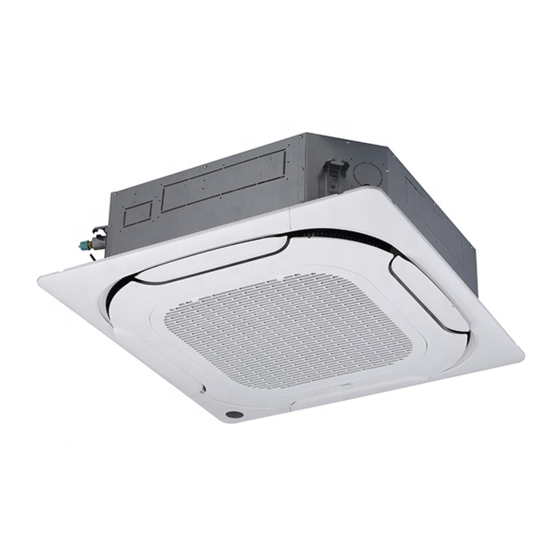
Installation and Operation Manual
Four-way Cassette
The 2nd generation DC VRF indoor unit
Original instructions
Thank you very much for purchasing our air conditioner.
Before using your air conditioner, please read this manual carefully and keep it for future reference.
Table of
Contents
Previous
Page
Next
Page
1
2
3
4
5
Advertisement
Table of Contents
Need help?
Do you have a question about the MI2-28Q4DHN1 and is the answer not in the manual?
Ask a question
Questions and answers
Related Manuals for Midea MI2-28Q4DHN1
Air Conditioner Midea MIV V4+ Mini Service Manual
Dc inverter r410a (68 pages)
Air Conditioner Midea MIS26 Owner's Manual
(20 pages)
Air Conditioner Midea MIS70 Owner's Manual
(20 pages)
Air Conditioner Midea MISSION Smart Series Owner's Manual
Split-type room air conditioner (60 pages)
Air Conditioner Midea MISSION Xtreme Series Owner's Manual
Split-type room air conditioner (60 pages)
Air Conditioner Midea Mini VRF Technical & Service Manual
(85 pages)
Air Conditioner Midea MI2-56Q4DHN1 Installation And Operation Manual
Four-way cassette the 2nd generation dc vrf indoor unit (25 pages)
Air Conditioner Midea MISSION2 3D INVERTER Series Service Manual
(113 pages)
Air Conditioner Midea Mini VRF C Series Owner's Manual
(12 pages)
Air Conditioner Midea MIH15T2HN18 Engineering Data
Medium static pressure duct vrf idu (25 pages)
Air Conditioner Midea MIH15Q4CHN18 Installation And Operation Manual
Compact four-way cassette (100 pages)
Air Conditioner Midea MI2-56Q4DN1 Installation And Owner's Manual
Four-way cassette 2nd generation (22 pages)
Air Conditioner Midea MI2-71Q4DN1 Installation And Owner's Manual
Four-way cassette 2nd generation (22 pages)
Air Conditioner Midea MI-22Q4/DHN1-A3 Installation And Operation Manual
Compact four-way cassette (26 pages)
Air Conditioner Midea Mini C Series Service Manual
Commercial air conditioners (84 pages)
Air Conditioner Midea BREEZELESS Technical Manual
R32 3d inverter control (46 pages)
This manual is also suitable for:
Mi2-36q4dhn1
Mi2-45q4dhn1
Mi2-56q4dhn1
Mi2-71q4dhn1
Mi2-80q4dhn1
Mi2-90q4dhn1
...
Show all
Mi2-100q4dhn1
Mi2-112q4dhn1
Mi2-140q4dhn1
Table of Contents
Save PDF
Print
Rename the bookmark
Delete bookmark?
Delete from my manuals?
Login
Sign In
OR
Sign in with Facebook
Sign in with Google
Upload manual
Upload from disk
Upload from URL


Need help?
Do you have a question about the MI2-28Q4DHN1 and is the answer not in the manual?
Questions and answers