Table of Contents
Advertisement
Available languages
Available languages
Quick Links
T E C H N O L O G Y F O R T H E W E L D E R ´ S W O R L D .
DE Betriebsanleitung / EN Operating instructions
FR Mode d'emploi / ES Instructivo de servicio
MF1
DE Masterantrieb mit Drahtistwertgeber
EN Masterfeeder provided with wire actual value encoder
FR Entraînement maître avec transmetteur de valeur réelle
ES Devanadora o alimentador con indicador del valor actual
del hilo
EN 60 974-5
www.binzel-abicor.com
Advertisement
Chapters
Table of Contents

Subscribe to Our Youtube Channel
Related Manuals for Abicor Binzel MF1

Summary of Contents for Abicor Binzel MF1
- Page 1 T E C H N O L O G Y F O R T H E W E L D E R ´ S W O R L D . DE Betriebsanleitung / EN Operating instructions FR Mode d’emploi / ES Instructivo de servicio DE Masterantrieb mit Drahtistwertgeber EN Masterfeeder provided with wire actual value encoder FR Entraînement maître avec transmetteur de valeur réelle...
-
Page 2: Table Of Contents
Produktes erforderlich werden. Diese Änderungen werden jedoch in neuen Ausgaben berücksichtigt. Alle in der Betriebsanleitung genannten Handelsmarken und Schutzmarken sind Eigentum der jeweiligen Besitzer/Hersteller. Unsere aktuellen Produktdokumente, sowie alle Kontaktdaten der ABICOR BINZEL Ländervertretungen und Partner weltweit, finden Sie auf unserer Homepage www.binzel-abicor.com... -
Page 3: Identifikation
1 Identifikation 1 Identifikation Der MF1 ist Bestandteil des Drahtvorschubsystems MFS welches in der Industrie und im Gewerbe zur Förderung von Schweissdraht oder Lot im Laserbereich eingesetzt wird. Der MF1 ist ein 4-Rollen Drahtantrieb und dient ausschließlich als Masterantrieb. Alle weiteren, für den Fügeprozess notwendigen Medien (Kühlmittel, Schutzgas, Schweisstrom) sind separat zuzuführen. -
Page 4: Klassifizierung Der Warnhinweise
2 Sicherheit 2.4 Klassifizierung der Warnhinweise Die in der Betriebsanleitung verwendeten Warnhinweise sind in vier verschiedene Ebenen unterteilt und werden vor potenziell gefährlichen Arbeitsschritten angegeben. Geordnet nach abnehmender Wichtigkeit bedeuten sie folgendes: GEFAHR Bezeichnet eine unmittelbar drohende Gefahr. Wenn sie nicht gemieden wird, sind Tod oder schwerste Verletzungen die Folge. -
Page 5: Produktbeschreibung
3 Produktbeschreibung 3 Produktbeschreibung WARNUNG Gefahren durch nicht bestimmungsgemäße Verwendung Bei nicht bestimmungsgemäßer Verwendung können vom Gerät Gefahren für Personen, Tiere und Sachwerte ausgehen. • Gerät ausschließlich bestimmungsgemäß verwenden. • Gerät nicht eigenmächtig zur Leistungssteigerung umbauen oder verändern. • Gerät nur durch befähigte Personen (in Deutschland siehe TRBS 1203) verwenden. 3.1 Technische Daten Temperatur der Umgebungsluft - 10 °C bis + 40 °C... -
Page 6: Abkürzungen
3 Produktbeschreibung Gegen-EMK 5,40 V/1000Upm Drehmomentkonstante 52 mNm/A (7,3 oz-in) Anschlusswiderstand 2,20 Ohm Motorregulierung R/k² 0,83 10³/Nms Anschlußinduktivität 0,40 mH Rotorträgheitsmoment 71,4 kgm² x 10 Mechanische Zeitkonstante 6 ms Tab. 6 Motor motorspezifische Parameter Impulse pro Umdrehung Stromaufnahme typisch 10 mA max. -
Page 7: Typenschild
3 Produktbeschreibung 3.3 Typenschild Der Masterantrieb MF1 ist wie folgt gekennzeichnet: Gerätenummer Übersetzung i=30/1oder i=15/1 ist angegeben Abb. 1 Typenschild Beachten Sie für alle Rückfragen folgende Angaben: • Gerätenummer 3.4 Verwendete Zeichen und Symbole In der Betriebsanleitung werden folgende Zeichen und Symbole verwendet: Symbol Beschreibung •... -
Page 8: Lieferumfang
5 Funktionsbeschreibung Die zum Schweißprozess benötigten Medien Schweisstrom, Schutzgas, Kühlmittel und Ausblasluft werden durch den Masterantrieb MF1 geführt und zum Brenner weitergeleitet. Die Schnittstellen zum Brenner bzw. Schlauchpaket sind auf die anwendungsspezifischen Anforderungen abgestimmt. Der Masterantrieb MF1 wird mit einer Roboterhalterung am Roboter bzw. Abschaltsicherung befestigt. Der Vier Rollen Antrieb fördert den Draht in einer konstanten Drahtgeschwindigkeit. -
Page 9: Inbetriebnahme
6 Inbetriebnahme Schnittstelle als Druckluftkupplung Schlauchpaketkupplung Anschluss Steuerleitung 4 polig Schnittstelle Brenner Schnittstelle als Druckluftanschluss Schnittstelle WH ® Masterantrieb MF1 mit Drahtistwertgeber Anschluss Steuerleitung Schlauchpaket 19 polig 10 Schnittstelle ABIROB Schnittstelle Schlauchpaket Abb. 2 Funktionsbeschreibung 6 Inbetriebnahme GEFAHR Verletzungsgefahr durch unerwarteten Anlauf Für die gesamte Dauer von Wartungs-, Instandhaltungs-, Montage- bzw. -
Page 10: Vorschubrollen Montieren
6 Inbetriebnahme Schutzkappe Zahnradachsen 2Stk. Rändelschraube Antriebszahnräder Antriebszahnräder 4Stk. Exzenterbolzen Rändelschrauben-Antriebsrollen Andruckwippe 10 Drahtistwertgeber (ATV) Antriebszahnrad mit Nut Abb. 3 Inbetriebnahme 6.1 Vorschubrollen montieren HINWEIS • Achten Sie auf den richtigen Einbau der Rändelschrauben. Für Antriebsrollen und für Druckrollen verwenden. Auf richtigen Einbau der Vorschubrollen achten, für Antriebsrollen und für Druckrollen verwenden. -
Page 11: Antriebsrollen
6 Inbetriebnahme 6 Alle Teile in umgekehrten Reihenfolge wieder montieren. 6.1.2 Antriebsrollen Abb. 3 Inbetriebnahme auf Seite DE-10 HINWEIS • Antriebsrollen Rot = V-Nut / Antriebesrollen Blau = U-Nut / Antriebsrollen Grün = gerändelte V-Nut. • Eine eingeprägte Zahl gibt den zu verwendenden Drahtdurchmesser an. ... -
Page 12: Andruckkraft Einstellen
6 Inbetriebnahme 6.1.4 Andruckkraft einstellen Die Andruckkraft hat einen definierten Anfangs- und Endpunkt. Andruckwippe Schraube Hülse Markierung Abb. 5 Andruckkraft einstellen HINWEIS • Eine Umdrehung der Schaube (3) entspricht 80 N. Ist die Schraube (3) komplett eingeschraubt, ergibt sich eine Kraft von 200 N. Die Markierung (4) der Schraube (3) zeigt dabei nach oben und deckt sich mit der Markierung der Hülse (2). -
Page 13: Steckerbelegung Steuerleitung
Körperliche Schäden durch Drahtanfang. • Prozessseitigen Antrieb von dem Körper weg halten. 1 Schlauchpaket an Schnittstelle (6) anschließen und Schutzkappe nach oben abnehmen. Steuerleitungen an Masterantrieb MF1 anschließen. 2 Exzenterbolzen (3) drehen und nach oben herausnehmen. 3 Andruckwippe (8) öffnen. -
Page 14: Betrieb
7 Betrieb 7 Betrieb HINWEIS • Die Bedienung darf nur durch befähigte Personen (in Deutschland siehe TRBS 1203) erfolgen. • Überprüfen Sie das Schlauchpaket vor dem Anschließen an das Drahtvorschubgerät, ob entsprechend dem Drahtdurchmesser und der Drahtart die geeignete Drahtführung (Führungsspirale oder Kunststoffseele) eingesetzt ist. -
Page 15: Außerbetriebnahme
8 Außerbetriebnahme 8 Außerbetriebnahme HINWEIS • Da der Masterantrieb MF1 in ein Schweißsystem eingebunden ist, richtet sich die Außerbetriebnahme nach der Robotersteuerung. Beachten Sie dabei die Abschaltprozeduren aller im Schweißsystem vorhandenen Komponenten. 1 Robotersteuerung ausschalten. 9 Wartung und Reinigung Regelmäßige und dauerhafte Wartung und Reinigung sind Voraussetzung für eine lange Lebensdauer und eine einwandfreie Funktion. -
Page 16: Kontrolle Der Drahtführungsnippel
Drahtführungsnippel für Drahtführungsnippel zwischen Drahtführungsnippel am Drahtistwertgeber (Speedometer) den Antriebsrädern Drahtauslauf Masterliner Abb. 10 Drahtführungsnippel MF1 Drahtführungsnippel in Ordnung Drahtführungsnippel nicht in Ordnung, austauschen Abb. 11 Abnutzung Drahtführungsnippel 9.3 Wartungsintervalle HINWEIS • Die angegebenen Wartungsintervalle sind Richtwerte und beziehen sich auf den Einschichtbetrieb. -
Page 17: Störungen Und Deren Behebung
10 Störungen und deren Behebung Wöchentlich Monatlich • Sichtkontrolle der Drahtführungsnippel. 9.2 Kontrolle der Drahtführungsnippel auf Seite DE-16 Tab. 14 Wartungsintervalle 10 Störungen und deren Behebung GEFAHR Verletzungsgefahr und Geräteschäden durch unautorisierte Personen Unsachgemäße Reparaturen und Änderungen am Produkt können zu erheblichen Verletzungen und Geräteschäden führen. -
Page 18: Demontage
Betriebsmittelhersteller vorgegebenen Sicherheitsdatenblätter. Kontaminierte Reinigungswerkzeuge (Pinsel, Lappen usw.) müssen ebenfalls entsprechend den Angaben des Betriebsmittelherstellers entsorgt werden. 12.3 Verpackungen ABICOR BINZEL hat die Transportverpackung auf das Notwendigste reduziert. Bei der Auswahl der Verpackungsmaterialien wird auf eine mögliche Wiederverwertung geachtet. DE - 18... - Page 19 12 Entsorgung DE - 19...
- Page 20 All brand names and trademarks that appear in this manual are the property of their respective owners/manufacturers. Our latest product documents as well as all contact details for the ABICOR BINZEL national subsidiaries and partners worldwide can be found on our website at www.binzel-abicor.com...
-
Page 21: Identification
1 Identification 1 Identification The frontdrive MF1 is a wire feeding system that is used in industry and the trade for the automatic feeding of welding fillers. It essentially comprises a slave drive module with interfaces for cable assembly and media guide and an integrated control unit or data bus connections and a frontdrive. -
Page 22: Classification Of The Warnings
2 Safety 2.4 Classification of the warnings The warnings used in the operating instructions are divided into four different levels and are shown prior to potentially dangerous work steps. Arranged in descending order of importance, they have the following meaning: DANGER Describes an imminent threatening danger. -
Page 23: Product Description
3 Product description 3 Product description WARNING Hazards caused by improper use If improperly used, the device can present risks to persons, animals and material property. • Use the device according to its designated use only. • Do not convert or modify the device to enhance its performance without authorisation. •... -
Page 24: Abbreviations
3 Product description Back electromotive force 5,40 V/1000 rpm Torque constant 52 mNm/A (7.3 oz-in) Terminal resistance 2,20 Ohm Motor regulation R/k² 0,83 10³/Nms Terminal inductance 0,40 mH Rotor moment of inertia 71,4 kgm² x 10 Mechanical time constant 6 ms Tab. -
Page 25: Nameplate
3 Product description 3.3 Nameplate The frontdrive MF1 is marked as follows: Device number Transmission of i=30/1 or i=15/1 is specified Fig. 1 Nameplate When making any inquiries, please remember the following information: • Device number 3.4 Signs and symbols used... -
Page 26: Scope Of Delivery
The media required for the welding process welding current, shielding gas, coolant and blast air are passed through the frontdrive MF1 and fed to the torch. The interfaces with the torch and the cable assembly are adapted to the application-specific requirements. The frontdrive MF1 is fastened to the robot or the safety cut-out by means of a robot mount. -
Page 27: Putting Into Operation
Interface as compressed-air clutch Cable assembly clutch CAT robot mount Torch interface Interface as compressed-air connection 4-pin control lead connection Frontdrive MF1 provided with wire actual 19-pin connection of cable assembly 10 Interface WH ® value encoder control lead 11 Interface ABIROB Cable assembly interface Fig. -
Page 28: Mounting The Feed Rolls
6 Putting into operation Protection cap 2 x Toothed wheel axles Knurled screw Drive gears 4x Drive gears Eccentric bolt Pressure roll knurled screws Pressure rocker 10 Wire actual value encoder (ATV) Drive gear with groove Fig. 3 Putting into operation 6.1 Mounting the feed rolls NOTICE •... -
Page 29: Drive Rolls
6 Putting into operation 7 Remount all components in reverse order. 6.1.2 Drive rolls Fig. 3 Putting into operation on page EN-10 NOTICE • Red drive rolls = V-groove / blue drive rolls = U-groove / green drive rolls = knurled V-groove. •... -
Page 30: Setting The Contact Pressure
6 Putting into operation 6.1.4 Setting the contact pressure The contact pressure has a defined start and end point. Pressure rocker Screw Sleeve Mark Fig. 5 Setting the contact pressure NOTICE • One rotation of the screw (3) corresponds to 80 N. If the screw (3) is fully tightened, this corresponds to a force of 200 N. -
Page 31: Connector Assignment Of Control Lead
• Keep process-side drive away from the body. 1 Connect the cable assembly to the interface (6) and lift off the protection cap. Connect the control leads to the frontdrive MF1. 2 Rotate the eccentric bolt (3) and remove it upwards. -
Page 32: Operation
8 Putting out of operation NOTICE • As the MF1 frontdrive is integrated into a welding system, putting out of operation depends on the robot control system. Please make sure that the shutdown procedures for all components integrated in the welding system are strictly observed. -
Page 33: Maintenance And Cleaning
9 Maintenance and cleaning 9 Maintenance and cleaning Scheduled maintenance and cleaning is prerequisite for a long life and a trouble free operation. DANGER Risk of injury due to unexpected start-up. The following instructions must be adhered to for the entire duration of maintenance, servicing, mounting, dismounting and repair work: •... -
Page 34: Inspecting The Wire Guide Nipple
Wire guide nipple at the value encoder (speedometer) drive wheels Masterliner wire outlet Fig. 10 Wire guide nipple MF1 Wire guide nipple okay Wire guide nipple not okay – replace Fig. 11 Wear to the wire guide nipple 9.3 Maintenance intervals NOTICE •... -
Page 35: Troubleshooting
10 Troubleshooting Weekly Monthly • Visual inspection for abrasion or damage to the gears. 9.1 Wear to the toothed wheels on page EN-15 • Visual inspection of the wire guide nipple. 9.2 Inspecting the wire guide nipple on page EN-16 Tab. -
Page 36: Dismounting
Contaminated cleaning tools (brushes, rags, etc.) must also be disposed of in accordance with the information provided by the manufacturer of the consumables. 12.3 Packaging ABICOR BINZEL has reduced the packaging for shipping to a minimum.Packaging materials are always selected with regard to their possible recycling ability. EN - 18... - Page 37 12 Disposal EN - 19...
- Page 38 Toutes les marques déposées et marques commerciales contenues dans le présent mode d'emploi sont la propriété de leurs titulaires/fabricants respectifs. Vous trouverez nos documents actuels sur les produits, ainsi que l’ensemble des coordonnées des représentants et des partenaires d'ABICOR BINZEL dans le monde sur la page d'accueil www.binzel-abicor.com Identification FR-3...
-
Page 39: Identification
1 Identification 1 Identification L'entraînement maître MF1 est un système de dévidoir utilisé dans l'industrie et l'artisanat pour l'alimentation automatique des métaux d'apport. Il est composé d'un module d'entraînement esclave équipé des interfaces pour le faisceau et le passage des fluides ainsi que d'une commande intégrée avec des interfaces de données BUS et d'un entraînement maître. -
Page 40: Classification Des Consignes D'avertissement
2 Sécurité 2.4 Classification des consignes d’avertissement Les consignes d'avertissement utilisées dans le mode d'emploi sont divisées en quatre niveaux différents. Elles sont indiquées avant les étapes de travail potentiellement dangereuses. Elles sont classées par ordre d'importance décroissant et ont la signification suivante : DANGER Signale un danger imminent. -
Page 41: Description Du Produit
3 Description du produit 3 Description du produit AVERTISSEMENT Risques liés à l'utilisation non conforme aux dispositions Une utilisation non conforme aux dispositions de l'appareil peut entraîner un risque pour les personnes, les animaux et les biens matériels. • N'utiliser l'appareil que conformément à son emploi prévu. •... -
Page 42: Abréviations
3 Description du produit Force électromotrice antagoniste 5,40 V/1000 Tr/min Constante de couple 52 mNm/A (7,3 oz-in) Résistance de connexion 2,20 ohms Régulation du moteur R/k² 0,83 10³/Nms Inductance de connexion 0,40 mH Moment d'inertie du rotor 71,4 kgm² x 10 Constante de temps mécanique 6 ms Tab. -
Page 43: Plaque Signalétique
3 Description du produit 3.3 Plaque signalétique L'entraînement maître MF1 est caractérisé de la manière suivante : Numéro d’appareil Transmission i=30/1ou i=15/1 est indiquée Fig. 1 Plaque signalétique Pour tous renseignements complémentaires, les informations suivantes sont nécessaires: • Numéro d’appareil 3.4 Signes et symboles utilisés... -
Page 44: Matériel Fourni
à travers l'entraînement maître MF1 jusqu'à la torche de soudage. Les interfaces pour la torche de soudage et le faisceau sont adaptées aux exigences spécifiques à l'application. L'entraînement maître MF1 est fixé sur le robot ou sur le dispositif d'arrêt automatique à... -
Page 45: Mise En Service
Coupleur pour le faisceau Support robot pour CAT Interface torche de soudage Raccord d'air comprimé Raccord du câble de commande, 4 pôles Entraînement maître MF1 avec transmetteur Raccord du câble de commande du 10 Interface WH ® de valeur réelle faisceau, 19 pôles... -
Page 46: Monter Les Galets
6 Mise en service Coiffe de protection 2 axes de pignon Vis moletée Pignons de transmission 4 pignons de transmission Boulon excentrique Galets d'entraînement à vis moletée Support galet presseur 10 Transmetteur de valeurs réelles de fil (ATV) Pignon de transmission avec rainure Fig. -
Page 47: Galets D'entraînement
6 Mise en service 6 L'assemblage montage est effectué dans l'ordre inverse. 6.1.2 Galets d'entraînement Fig. 3 Mise en service Page FR-10 AVIS • Galets d'entraînement rouges = rainure en V / Galets d'entraînement bleus = rainure en U / Galets d'entraînement verts = rainure en V moletée. -
Page 48: Régler La Force De Pression
6 Mise en service 6.1.4 Régler la force de pression La force de pression a un point initial et un point final définis. Support galet presseur Douille Marquage Fig. 5 Régler la force de pression AVIS • Un tour de la vis (3) correspond à 80 N. Si la vis (3) est entièrement vissée, la force est de 200 N. -
Page 49: Affectation Des Connecteurs Du Câble De Commande
• Maintenir une certaine distance entre l'entraînement côté processus et le corps. 1 Raccorder le faisceau à l'interface (6) et enlever la coiffe de protection par le haut. Raccorder le câble de commande à l'entraînement maître MF1. 2 Tourner le boulon excentrique (3) et l'enlever par le haut. -
Page 50: Fonctionnement
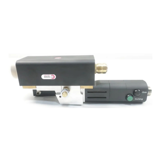
7 Fonctionnement 7 Fonctionnement AVIS • La commande est réservée aux personnes autorisées (en Allemagne, voir TRBS 1203). • Avant de raccorder le faisceau au dévidoir, contrôlez si une gaine guide-fil (gaine guide-fil acier ou gaine guide-fil synthétique) adapté au diamètre et au type du fil est montée. 7.1 Eléments de commande Bouton pre-gaz (noir) Raccord du câble de commande... -
Page 51: Mise Hors Service
8 Mise hors service AVIS • Lorsque l'entraînement maître MF1 est intégré dans un système de soudage, la mise hors service dépend de la commande du robot. Observez aussi les processus de mise hors service des éléments intégrés dans le système de soudage. -
Page 52: Usure Des Pignons
Masterliner (tachymètre) Fig. 10 Tube amenée de fil MF1 Tube amenée de fil fonctionnel Tube amenée de fil non fonctionnel, à remplacer Fig. 11 Usure du tube amenée de fil FR - 16... -
Page 53: Intervalles De Contrôle
9 Entretien et nettoyage 9.3 Intervalles de contrôle AVIS • Les intervalles d'entretien indiqués sont des valeurs approximatives se rapportant à un fonctionnement par équipes de 8 h. • Effectuez une inspection visuelle hebdomadaire des pignons. • Une force de réglage élevée du support galet presseur entraîne une accélération de l'usure des pignons. -
Page 54: Dépannage
10 Dépannage 10 Dépannage DANGER Danger de blessures et dommages sur les appareils causés par des personnes non autorisées Les réparations et modifications non conformes du produit peuvent entraîner des blessures graves ainsi que des dommages considérables de l'appareil. Les effets de la garantie produit cessent en cas d'intervention par des personnes non autorisées. -
Page 55: Démontage
(pinceau, chiffon etc.) doivent être également éliminés selon les indications du fabricant des produits consommables. 12.3 Emballage ABICOR BINZEL a réduit l'emballage de transport au nécessaire. Lors du choix des matériaux d'emballage, veiller à ce que ces derniers soient recyclables. FR - 19... - Page 56 Todas las marcas comerciales y marcas registradas mencionadas en este instructivo de servicio son propiedad del correspondiente propietario/fabricante. Para obtener la documentación actual sobre nuestros productos así como para conocer los datos de contacto de los representantes locales y socios de ABICOR BINZEL en todo el mundo, consulte nuestra página de inicio en www.binzel-abicor.com Identificación ES-3 Operación...
-
Page 57: Identificación
1 Identificación 1 Identificación El máster MF1 es una devanadora que se utiliza en la industria y los oficios para transportar los aditivos de soldadura en modo automático. Generalmente está compuesto por un módulo de accionamiento, tipo esclavo, con interfaces para el conjunto de cables y el transporte de los medios así como un control integrado o conexiones para el bus de datos y un máster. -
Page 58: Clasificación De Las Advertencias
2 Seguridad 2.4 Clasificación de las advertencias Las advertencias empleadas en este Instructivo de servicio se dividen en cuatro niveles diferentes y se indican antes de operaciones potencialmente peligrosas. Ordenadas de mayor a menor importancia, significan lo siguiente: ¡PELIGRO! Indica un peligro inminente. Si no se evita, las consecuencias son la muerte o lesiones muy graves. ¡ADVERTENCIA! Indica una situación posiblemente peligrosa. -
Page 59: Descripción Del Producto
3 Descripción del producto 3 Descripción del producto ¡ADVERTENCIA! Peligros por utilización diferente a la prevista En caso de una utilización diferente a la prevista, podrían derivarse del aparato peligros para personas, animales y bienes. • Utilice el aparato únicamente conforme a lo previsto. •... - Page 60 3 Descripción del producto Contrafuerza electromotriz 5,40 V/1000 rpm Constante de par de giro 52 mNm/A (7,3 oz-in) Resistencia de conexión 2,20 ohmios Regulación del motor en R/k² 0,83 10³/Nms Inductancia de conexión 0,40 mH Momento de inercia del rotor 71,4 kgm²...
-
Page 61: Abreviaciones
ROBO WH Interfaz de diferentes antorchas Tab. 9 Abreviaciones 3.3 Placa de identificación El máster MF1 está marcado como sigue: Número de aparato La transmisión i=30/1 ó i=15/1 está especificada Fig. 1 Placa de identificación Indique los datos siguientes si se pone en contacto con nosotros para cualquier pregunta: •... -
Page 62: Relación De Material Suministrado
El máster MF1 se fija en el robot o el sistema anticolisión del robot mediante un soporte. El accionamiento de cuatro rodillos transporta el hilo a una velocidad constante. El máster asume la función de empuje. -
Page 63: Puesta En Servicio
Conexión del cable de control, 4 polos Interfaz con la antorcha Conexión del cable de control y del 10 Interfaz WH ® Máster MF1 con indicador del valor actual conjunto de cables, 19 polos 11 Interfaz ABIROB del hilo Interfaz para el conjunto de cables Fig. -
Page 64: Montar Los Rodillos
6 Puesta en servicio Tapón de protección 2 ejes de rueda dentada Tornillo moleteado Ejes reductores 4 ejes reductores Perno excéntrico Tornillos moleteados para rodillos de arrastre Soporte para rodillos de presión 10 Transmisor de valor real de alambre (ATV) Eje reductor con ranura Fig. -
Page 65: Rodillos De Arrastre
6 Puesta en servicio 6 Montar todas las piezas de nuevo en orden inverso. 6.1.2 Rodillos de arrastre Fig. 3 Puesta en marcha en página ES-10 AVISO • Rodillos de arrastre de color rojo = ranura en V / rodillos de arrastre de color azul = ranura en U / rodillos de arrastre de color verde = ranura en V moleteada. -
Page 66: Ajustar La Fuerza De Presión
6 Puesta en servicio 6.1.4 Ajustar la fuerza de presión La fuerza de presión tiene un punto de inicio y final definido. Soporte para rodillos de presión Tornillo Casquillo Marca Fig. 5 Ajustar la fuerza de presión AVISO • Una vuelta del tornillo (3) corresponde a 80 N. Si el tornillo (3) está... -
Page 67: Asignación De Pines Para El Cable De Control
• Mantener accionamiento de proceso lejos del cuerpo. 1 Conectar el conjunto de cables a la interfaz (6) y extraer el tapón de protección hacia arriba. Conectar los cables de control a la devanadora o alimentador MF1. 2 Girar el perno excéntrico (3) y extraerlo hacia arriba. -
Page 68: Operación
7 Operación 7 Operación AVISO • Al equipo sólo lo pueden manejar personas cualificadas (en Alemania, véase TRBS 1203). • Comprobar el conjunto de cables antes de conectarlo a la devanadora. Asegúrese de que se haya insertado la guía de hilo (guía de alambre o sirga) conforme al diámetro y tipo del hilo. 7.1 Elementos de mando Gatillo para el test de gas Conexión del cable de control y... -
Page 69: Desconexión De La Antorcha
8 Desconexión de la antorcha AVISO • Dado que el máster MF1 está integrado en un sistema de soldadura, la desconexión es determinada por el control de robot. Observar también la desconexión de todos los componentes integrados en el sistema de soldadura. - Page 70 Masterliner (velocímetro) Fig. 10 Boquilla de la guía de alambre MF1 Boquilla de la guía de alambre correcta Boquilla de la guía de alambre no correcta, sustituir Fig. 11 Desgaste de la boquilla de la guía de alambre 9.3 Intervalos de mantenimiento...
-
Page 71: Revisiones De La Boquilla De La Guía De Alambre
10 Averías y su eliminación Comprobar lo siguiente: Semanalmente Mensualmente • Se recomienda una limpieza general; en caso de condiciones de • Lubricar de aceite todas las piezas móviles y rodamientos trabajo extremas es necesaria. de los rodillos con aceite lubricante adecuado. •... -
Page 72: Desmontaje
12.3 Embalajes ABICOR BINZEL ha reducido el embalaje de transporte a un mínimo necesario. Al seleccionar los materiales de embalaje, se tiene en cuenta un posible reciclaje. - Page 73 Notizen /Notes/Notes/Notas Notizen/Notes/Notes/Notas ES - 19...
- Page 74 Notizen /Notes/Notes/Notas ES - 20...
- Page 75 Notizen /Notes/Notes/Notas ES - 21...
- Page 76 T E C H N O L O G Y F O R T H E W E L D E R ´ S W O R L D . Alexander Binzel Schweisstechnik GmbH & Co.KG Postfach 10 01 53 • D–35331 Giessen Tel.: ++49 (0) 64 08 / 59–0 Fax:...
Need help?
Do you have a question about the MF1 and is the answer not in the manual?
Questions and answers