Table of Contents
Advertisement
Mounting Instructions
R
i
July 2014
NMkit5000_GB-A
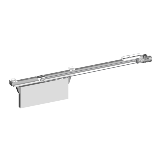
KIT 5000
For manual Fermatic systems:
2120 / 2130 / 2150 - 2320 / 2420
3430 / 3530 / 7530
2120 / 2130 / 2150
2320 / 2420
3430 / 3530 / 7530
Power supply : 220-240V AC
50/60 Hz monophase
Motor power : 400W (24Vcc)
This instructions manual includes the mounting, utilization and the maintenance instructions. We recommend to read this carefully and to place it at the user's
disposal. The english version of our general conditions of sales and mounting instructions are not binding, and are only given for information purposes.
Only the french version can be used in case of legal action.
Kit5000_GB-A
- 1 -
Advertisement
Table of Contents

Related Manuals for FERMOD KIT 5000

Summary of Contents for FERMOD KIT 5000
- Page 1 Mounting Instructions July 2014 NMkit5000_GB-A KIT 5000 For manual Fermatic systems: 2120 / 2130 / 2150 - 2320 / 2420 3430 / 3530 / 7530 2120 / 2130 / 2150 2320 / 2420 3430 / 3530 / 7530 Power supply : 220-240V AC...
-
Page 2: Table Of Contents
SUMMARY 1 - General informations....................1.1 - Regulations and obligations................1.2 - Liabilities......................2 - Transport........................3 - Storage........................4 - Mounting precautions..................... 5 - Characteristics......................FERMATIC 2120 / 2130 / 2150 - 2320 / 2420 SYSTEMS 6 - Mounting onto 2120 / 2130 / 2150 - 2320 / 2420 systems........6.1 - Rail preparing.................... -
Page 3: General Informations
EN 12428 Thermal transmission FERMOD has taken the standards that apply to the supplied products into consideration. FERMOD has taken the standards that apply to the supplied products into consideration. FERMOD has taken the standards that apply to the supplied products into consideration. -
Page 4: Transport
The original packing is designed for all types of transportation means. The packed kit withstands stacking of 4 others automatic kits. The liability of FERMOD ceases: - as soon as the customer or installer opens the package or a part of the packaging, - as soon as the package has suffered a considerable impact in such a way that it’s damaged. -
Page 5: Characteristics
5 - CHARACTERISTICS AUTOMATIC ELECTRONIC KIT 5000 The automatic electronic kit 5000 is designed to motorize the Fermatic manual systems: 2120 / 2130 / 2150 2320 / 2420 3430 3530 / 7530 These manual systems are used for horizontal sliding doors with defined characteristics (iso-thermal, acoustical, clean room, dust-tight…). - Page 6 Parts list / Tools Designation Belt adjuster Adjuster screws 2120/30/50 - 2320 - 2420 Adjuster screws 3430 - 3530 - 7530 Door driving assembly Driving assembly screws 3430 - 3530 - 7530 Motor unit Motor screws 2120/30/50 - 2320 - 2420 Motor screws 3430 - 3530 - 7530 Belt Command box...
- Page 7 Dimensions 2120 / 2130 / 2150 166* 183** 2120 : X = door width 2130/2150 : 2320 / 2420 X = door width 3430 / 3530 / 7530 3430 : X = door width 3530/7530 : 3430 / 3530 / 7530 2120 3431 3432...
- Page 8 MOUNTING ONTO 3430 / 3530 / 7530 SYSTEMS ....See page CAUTION • Installation of the Kit 5000 is the same regardless of the opening side of the door. It’s recommended to install the motor right side of the rail.
-
Page 9: Rail Preparing
RAIL PREPARING 2120 / 2130 / 2150 2320 / 2420 C = for cover M = for motor T = for belt adjuster 1 - Remove the 2 end covers. 2 - Insert the screws into the upper groove of the rail (see drawings below). BELT ADJUSTER Kit5000_GB-A - 9 -... -
Page 10: Door Driving Assembly
Ø 8 DOOR/OUTSIDE Nota : When mounting a Kit 5000 onto a manual Fermatic system already installed: wedge the door, unscrew the 2 door brackets (A) and push them aside to access the upper edge of the door. Fixing 5 countersunk screws Ø... - Page 11 90° MOTOR MOUNTING See page MOTOR LEFT SIDE MOTOR MOUNTING See page 2120 / 2130 / 2150 SYSTEMS 2120-2130 2150 Shoulder to the top ≈ 1 5 ≈ 1 5 2 0 6 2 0 6 Imperative 1 - Right side of the rail, remove the screw of the end bracket (2120/2130 systems). 2150 system : remove the left screw of the end bracket.
- Page 12 2320 / 2420 SYSTEMS Shoulder to the top 1 - Right side of the rail, remove the left screw of the end bracket and the left screw of the butt bracket. 2 - Replace the screw of the end bracket with spacer (B) from small bag (M7).
- Page 13 BELT Link belt/door 1 - Unscrew the 4 screws of the driving assembly flange. 2 - Engage the belt into the flange to its middle. 3 - Tighten the 2 screws of the flange to block the belt. 4 - Remove the belt guide (A). 5 - Engage the belt around the motor pulley, then around the belt adjuster pulley.
- Page 14 Tighten the belt 1 - Remove cover (A) with a screw- driver 2 - Loosen screw (B) of about 1/4turn 3 - Tighten the screw (C) of the belt adjuster to tighten the belt: the upper strand (D) must be horizontal. 4 - When the belt is tensioned, block the screw (B) .
-
Page 15: Motor
MOUNTING ONTO 2120 / 2130 / 2150 - 2320 / 2420 SYSTEMS ....See page CAUTION • Installation of the Kit 5000 is the same regardless of the opening side of the door. It’s recommended to install the motor right side of the rail. -
Page 16: Belt Adjuster
BELT ADJUSTER 3530 7530 3430 1 - Insert the 2 screws from small bag (M3) into 2 slots of the rail: 600mm (4th and 5th slot) to central bracket (see drawing below). 2 - Fix the belt adjuster (M1) on the top of the rail. Block the 2 screws. -
Page 17: Door Driving Assembly
DOOR DRIVING ASSEMBLY When mounting a Kit 5000 onto a manual Fermatic system already installed: 1 - Wedge the door. 2 - Remove the right end cover of the mobile part. 3 - Unscrew the door bracket/right side (A) to remove it . -
Page 18: Motor
MOTOR 90° MOTOR MOUNTING See page LEFT SIDE MOTOR MOUNTING See page The motor mounting depends on Manual Fermatic system (3430 or 3530/7530) and butt model mounted onto the rail. There are 5 different ways to mount the motor: 3 5 3 0 3 5 3 0 7 5 3 0 7 5 3 0... - Page 19 PUSH THE DOOR LEFT SIDE CASE N°1 - FERMATIC 3430 1 - Right side of the rail, remove the screw of the end bracket. 2 - Replace the screw of the end bracket with a screw and the spacer (B) from small bag (M8).
- Page 20 DOOR CLOSED CASE N°2 - FERMATIC 3530 / 7530 1 - Right side of the rail, remove the screw of the end bracket. 2 - Replace the screw of the end bracket with a screw and the spacer (B) from small bag (M8).
- Page 21 DOOR CLOSED CASE N°3 - FERMATIC 3530 / 7530 1 - Right side of the rail, remove the screw of the end bracket. 2 - Replace the screw of the end bracket with a screw and the spacer (B) from small bag (M8). Block screw and spacer.
- Page 22 DOOR CLOSED CASE N°4 - FERMATIC 3530 / 7530 1 - Right side of the rail, remove the butt/opening side (C) under the end bracket. Keep its fixing nut (D). 2 - Block nut (D) on a screw from small bag (M8). 3 - Mount butt/opening side (C) with the screw and nut (D) and spacer (B).
- Page 23 DOOR OPEN CASE N°5 - FERMATIC 3530 / 7530 1 - Right side of the rail, remove the butt/opening side (C) under the end bracket. 2 - Mount butt/opening side (C) with a screw and spacer (B) from small bag (M8). Block. 3 - Left side of the end bracket, mount spacer (A) with the second screw from (M8) into the first hole of the rail.
-
Page 24: Belt
BELT Link belt/door 1 - Unscrew the 4 screws of the driving assembly flange. 2 - Engage the belt into the flange to its middle. 3 - Tighten the 2 screws of the flange to block the belt. 4 - Remove the belt guide (A). 5 - Engage the belt around the motor pulley, then around the belt adjuster pulley. - Page 25 Tighten the belt 1 - Remove cover (A) with a screwdriver 2 - Loosen screw (B) of about 1/4turn 3 - Tighten the screw (C) of the belt adjuster to tighten the belt: the upper strand (D) must be horizontal. 4 - When the belt is tensioned, block the screw (B) .
-
Page 26: Motor Mounting
8 - 90° MOTOR MOUNTING Depending on the system installation, the space available in the right end rail can be short for mounting the motor in its standard configuration . In that event it’s possible to mount the motor in 90° direction. Fermatic Fermatic 2120-2130-2150... - Page 27 90° Rotate 90° to the motor. Mount the motor on it’s bracket. Fix the belt guide (A). Fermatic Fermatic 2120-2130-2150 3430 2320-2420 3530-7530 Follow step 6.5 Follow step 7.4 . Belt mounting and tighten page page Kit5000_GB-A - 27 -...
-
Page 28: Left Side Motor Mounting
9 - LEFT SIDE MOTOR MOUNTING Depending on the system installation, the space available in the right end rail can be short for mounting the motor in its standard configuration . In that event it’s possible to mount the motor left side of the rail. Nota: The left side motor mounting is the same regardless of the opening side of the door. - Page 29 Mount the motor on it’s bracket. Fix the belt guide (A). Left side motor mounting WARNING For a left side motor mounting, it’s necessary to reverse the belt adjuster (M1) position and the driving assembly (M4) position compared with standard mounting. To mount the different parts of the Kit, see the drawings next page.
- Page 30 2120 / 2130 / 2150 SYSTEMS Belt adjuster Driving assy See 6.1 - 6.2 See 6.3 page page Central Bracket Motor Belt See 6.4 See 6.5 page page 3430 / 3530 / 7530 SYSTEMS Belt adjuster Driving assy See 7.1 See 7.2 page page...
Need help?
Do you have a question about the KIT 5000 and is the answer not in the manual?
Questions and answers