Table of Contents
Advertisement
Quick Links
Advertisement
Table of Contents

Subscribe to Our Youtube Channel
Related Manuals for Ronetix PEEDI

Summary of Contents for Ronetix PEEDI
- Page 1 PEEDI Powerful Embedded Ethernet Debug Interface User’s Manual Version 3.0...
- Page 2 February, 2019 Ronetix has made every attempt to ensure that the information in this document is accurate and complete. However, Ronetix assumes no responsibility for any errors, omissions, or for any consequences resulting from the use of the information included herein or the equipment it accompanies.
-
Page 3: Table Of Contents
1.1 PEEDI in the development process..................12 1.1.1 Single developer environment..................12 1.1.2 Multiple developers environment..................13 1.2 PEEDI in the manufacturing process..................13 1.2.1 PEEDI as a standalone FLASH programmer..............14 1.2.2 PEEDI as a device tester....................15 1.2.3 High productivity with the Multi Program feature............15 2 Installation............................15 2.1 Hardware installation.......................16... - Page 4 COREn_WORKSPACE....................34 COREn_DATASPACE....................34 COREn_PATH.........................34 COREn_FILE........................34 COREn_LOCKOUT_RECOVERY................35 COREn_OS........................36 Section PLATFORM_ARM and PLATFORM_ARM11.............36 COREn..........................36 COREn_VECTOR_CATCH_MASK................36 COREn_DCC_PORT......................37 COREn_USE_FAST_DOWNLOAD................37 COREn_BREAK_PATTERN..................37 Section PLATFORM_Cortex & Section PLATFORM_Cortex_SWD........38 COREn..........................38 COREn_APSEL......................38 COREn_DEBUG_ADDR....................39 COREn_DAPPC......................39 COREn_PERIODIC_TASK....................39 COREn_SWO........................40 COREn_PROFILING......................40 Section PLATFORM_XSCALE...................41 COREn..........................41 COREn_USE_FAST_DOWNLOAD................41 COREn_DEBUG_HANDLER_ADDR................41 COREn_VECTOR/RELOCATED_UNDEF/SWI/PABORT/DABORT/RES/IRQ/FIQ.42 Section PLATFORM_MPC5200..................43 COREn..........................43 COREn_BOOT_ADDR....................43 COREn_MEMDELAY....................43 Section PLATFORM_MPC5500..................43 COREn..........................44 COREn_NEXUS3_ACCESS..................44 MPC5XXX_AUX_TAP_CMD, COREn_AUX_TAP_CMD.........44...
- Page 5 CORE..........................49 CORE_MEMMAP......................49 Section PLATFORM_BLACKFIN..................50 COREn..........................50 COREn_VMEM......................51 COREn_VMEM_WINDOW...................51 COREn_VMEM_PINS....................51 CORE_MEMMAP......................52 Section PLATFORM_MIPS....................52 COREn..........................52 Section PLATFORM_AVR32....................53 COREn..........................53 COREn_BLOCK_ACCESS....................53 Section INIT.........................53 Section FLASH........................54 NOR FLASH programming....................55 I2C Programming......................55 SPI FLASH programming....................56 NAND FLASH programming..................57 OneNAND FLASH programming...................59 MMC/SD card programming...................59 Atmel SAM3/SAM4 programming.................59 Atmel AVR32UC3 programming..................59 Freescale Kinetis programming..................60 TI/Luminary LM3S programming...................60...
- Page 6 SET_VECTORS_CHECKSUM..................71 DATA_BANK........................72 BANK_SIZE........................72 F2F4_PSIZE........................72 PROTECTION_KEY0 – PROTECTION_KEY3............72 ALLOW_ZERO_KEYS....................73 CPU..........................73 SPI_DIV..........................74 nSPI..........................74 nCS..........................74 SPI_SPCK, SPI_MISO, SPI_MOSI, SPI_CS..............74 CMD_BASE........................75 DATA_BASE........................75 ADDR_BASE........................75 CS_ASSERT/RELEASE....................76 ALE_ASSERT/RELEASE....................76 CLE_ASSERT/RELEASE....................76 BAD_BLOCK_TABLE....................76 BAD_BLOCKS.......................77 ERASE_BAD_BLOCKS....................77 SWAP_BI.........................77 OOB_INFO........................77 DAVINCI_UBL_DESCIPTOR_MAGIC................79 DAVINCI_UBL_DESCIPTOR_ENTRY_POINT............79 DAVINCI_UBL_DESCIPTOR_LOAD_ADDR.............80 DAVINCI_UBL_MAX_IMAGE_SIZE................80 NUM_ECC........................80 HEADER.........................80 IPS_BASE........................81 SPIFI_BASE........................81 NCB_DATA........................81 LDLB_DATA........................81 SERIAL_NUM........................82 I2C_ADDR........................83 I2C_DELAY........................83 SDA_SET/CLR, SDA_IN/OUT, SDA_READ, SCL_SET/CLR........83 CS_ASSERT/RELEASE, SCLK_SET/CLR, MOSI_SET/CLR, MISO_READ....83 Section OS..........................84...
- Page 7 3.6.2 ST STM32 family......................88 3.6.3 Intel XScale family......................89 3.6.4 Freescale PowerQUICC II Pro MPC83XX family............90 3.6.5 Analog Devices Blackfin family..................91 3.7 Boot sequence..........................91 3.8 Multiple core support.......................94 3.9 Script execution using the front panel interface..............96 3.10 Serial Interface........................98 3.11 ARM DCC Interface......................98 3.12 Working with gdb........................99 3.13 Debugging Linux kernel......................101 3.14 Target OS thread awareness....................102...
- Page 8 memory multi load......................129 memory verify........................130 memory dump........................130 memory management......................131 memory test........................132 flash............................132 flash set..........................133 flash blank..........................133 flash erase...........................133 flash lock..........................134 flash unlock........................135 flash query..........................135 flash program........................136 flash multi erase........................136 flash multi blank.........................137 flash multi program......................138 flash verify..........................139 flash multi verify........................139 flash dump..........................140 flash read..........................141 flash info..........................141...
- Page 9 3.16 Multiple FLASH support.....................164 3.17 Working with a MMC/SD memory card................164 3.18 JTAG cable adapters......................165 3.19 PEEDI licenses........................166 4 Specifications..........................167 4.1 JTAG Target connector signals....................168 4.2 RS232 Connector (DB9F, female)..................170 4.3 Schematics..........................170 5 Warranty............................170 6 PEEDI Package contents.......................171 7 FAQ...............................171 8 Glossary............................176...
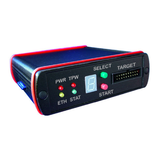
- Page 10 Figure 1.2: Multiple developers environment..................13 Figure 1.3: FLASH programmer with PC..................14 Figure 1.4: FLASH programmer without PC..................14 Figure 1.5: Multi board programming....................15 Figure 2.1: PEEDI Front Panel......................16 Figure 2.2: PEEDI Rear Panel......................16 Figure 2.3: Direct host connection.....................17 Figure 2.4: LAN connection.......................17 Figure 2.5: Target connection......................17...
-
Page 11: Peedi
The PEEDI will help to reduce Time-To-Market and increase the quality of the end product. PEEDI is a debugging and development tool that provides the ability to see what is taking place in the target system and control its behavior. PEEDI provides the services needed to perform all debugging operations. -
Page 12: Peedi In The Development Process
(TFTP, FTP or HTTP) allowing PEEDI to retrieve configuration files or executable images. In this (Figure 1) configuration the developer’s PC must be connected to PEEDI in a common LAN using crossover patch cable or by Ethernet via hub/switch. -
Page 13: Multiple Developers Environment
1.2 PEEDI in the manufacturing process PEEDI can be used in the manufacturing process as a tool for testing the device after it is assembled and as a FLASH programmer to program the device firmware. In both scenarios the host computer is not required because all the operations can be formed as script files and executed using the PEEDI’s front panel interface. -
Page 14: Peedi As A Standalone Flash Programmer
1.2.1 PEEDI as a standalone FLASH programmer PEEDI can be used as a FLASH programmer in two ways: The first way ( Figure 1.3: FLASH programmer with PC) is to connect to PEEDI via telnet • and execute FLASH command and script files from the command line interface (CLI). This method enables users to see all the status messages in an easy, understable format i.e. -
Page 15: Peedi As A Device Tester
Introduction 1.2.2 PEEDI as a device tester Here the PEEDI can be used in the same manner as in the previous section - making telnet connection or through the front panel interface. Depending on the specifics of what is to be tested two options can be applied: Execute commands that directly make some sort of test i.e. -
Page 16: Hardware Installation
Figure 2.2: PEEDI Rear Panel 2.1.1 Connection instructions To connect the PEEDI interface unit to your host and to the target hardware: Connect the host computer to an Ethernet network or directly to the PEEDI as required: • ◦ Direct host connection PEEDI User’s Manual... -
Page 17: Figure 2.3: Direct Host Connection
Connect the PEEDI interface unit to the target hardware, using the supplied JTAG adapter • and cable. The JTAG adapter must be on the PEEDI side of the JTAG cable. If your target JTAG port pinout is not standard, you may need to make your own target cable considering the PEEDI JTAG connector pinout. -
Page 18: Software Installation
Installation When PEEDI boots, if you have a terminal connected to the RS232 port of PEEDI you will • see various status messages. 2.2 Software installation See ’Cross development with GNU toolchain and Eclipse’: http://download.ronetix.at/toolchains/arm/arm_cross_development_guide.pdf Using PEEDI This chapter will explain PEEDI’s operating modes, PEEDI’s interface and the basic steps of configuring the software tools for working with PEEDI. -
Page 19: Setup With Redboot
13 Ethernet port 3.2 Setup with RedBoot RedBoot is a bootstrap loader, which during normal boot-up is used to load and launch PEEDI’s executable image. RedBoot is also used to update PEEDI’s firmware and to configure network PEEDI User’s Manual... -
Page 20: Redboot Configuration
RS232 port using a serial straight-through cable with DB9M (male) and DB9F (female) connectors on each end. Next step is to restart PEEDI by pressing the RESET button while holding both front panel buttons in. This will tell RedBoot not to load and launch the PEEDI executable if available, but to wait for connection on RS232 or Ethernet. -
Page 21: Firmware Update Procedure
3.3 Firmware update procedure First of all you need to reset PEEDI by pressing the RESET button on the back while holding both front panel buttons in. This will tell RedBoot not to load and launch the PEEDI executable, but to wait for connection on RS232 or Ethernet. -
Page 22: Update Via Rs232
RedBoot to start listening on RS232 port for incoming packets. Next tell your terminal application to start downloading the PEEDI firmware. 3.3.2 Update via Ethernet Now you may use update command to update the PEEDI firmware. You can update using TFTP, HTTP. The syntax of the update command is: update [FILEPATH | NUMBER]... - Page 23 In this case the command will be expanded to: RedBoot> update tftp://server_ip/file.bin where ‘server_ip’ is defined with ‘fconfig’. After you enter the command using your specific conditions, if the host is accessible and the file is present you should see this: PEEDI User’s Manual www.ronetix.at...
-
Page 24: Redboot Commands Used With Peedi
Syntax: update [FILEPATH | [NUMBER]] Description: Update PEEDI firmware. If no argument is provided last used will be taken. Default first used argument is taken when fconfig command is used. The update 1 command downloads the latest firmware image. PEEDI User’s Manual... -
Page 25: Config
- file path of the file FILE - filename which will be expanded to tftp://server_ip/FILE, where ‘server_ip’ is defined with ‘fconfig’ Example: config tftp://192.168.1.1/file.cfg config ftp://user:password@server/sub_directory/filename.cfg config http://server/sub_directory/filename.cfg config card://sub_directory/filename.cfg config file.cfg ; expanded to tftp://server_ip/file.cfg memtest PEEDI User’s Manual www.ronetix.at... -
Page 26: Configure Peedi
Configuration’. Note : A new PEEDI is set by the factory to get its network settings from a DHCP server. You can see the PEEDI IP by pressing and holding the green button on the front PEEDI panel. The IP will be shown on the front panel LED indicator. Or connect to PEEDI on the RS232 and the IP is shown during boot-up. -
Page 27: Section License
This section describes the protocol used with the host debugger. One debugger protocol is supported: the GDB Remote debug protocol. PROTOCOL Synopsis: PROTOCOL = gdb_remote Description: Describes the debugger protocol. If several protocols need to be enabled, they must be enumerated on the same line, separated by comma. PEEDI User’s Manual www.ronetix.at... -
Page 28: Remote_Port
FLASH0 = FLASH_NAND - FLASH section to be used for core 0 FLASH1 = FLASH_NAND - FLASH section to be used for core 1 Section TARGET This section describes the target’s platform. PLATFORM Synopsis: PLATFORM = ARM|ARM11|AVR32|Blackfin|ColdFire|Cortex-A| Cortex-M|Cortex-M_SWD|JBC_Player|MIPS|MPC5200|MPC5500| MPC8300|MPC8500|QorIQ_P|XScale Description: Target’s platform Example: [TARGET] PLATFORM = ARM PEEDI User’s Manual www.ronetix.at... -
Page 29: Section Platform_Xxx - Parameters For All Targets With Jtag Interface
Length of IRs (Instruction Registers) of the devices on the JTAG chain. All IRs must be enumerated; the ones not supported by PEEDI must be skipped when defining COREn parameters (see below). If AUTO X is used first, then PEEDI will try to auto detect the actual number of TAPs connected in the JTAG chain. -
Page 30: Reset_Time
RESET_TIME = <milliseconds> Description: If 0 is specified, no reset will be issued, this way PEEDI can be attached to already initialized and running target, so INIT section could also be missing. If the target executes code after reset even CORE_STARTUP_MODE=RESET, this means the TAP is not active during reset. -
Page 31: Wakeup_Time
Type of CORE and a TAP number separated by comma. Every core must be defined with the COREn parameter, where ’n’ is a number; each parameter related to this core must be preceded with the same COREn prefix. PEEDI User’s Manual www.ronetix.at... -
Page 32: Coren_Startup_Mode
RESET - Force the target to debug mode immediately out of reset. No code is • executed after reset. (default mode) STOP, XX - After power-up PEEDI waits XX ms (this gives time to the target • to execute its own initialization code) and target is placed in debug mode (halted). -
Page 33: Coren_Endian
’single step’, ’step in’ and ’step out’, but if you have set two watch or break points, only ’continue’ is possible after the target breaks, since the debugger needs a temporary break point to achieve the ’step’ functionality. PEEDI User’s Manual www.ronetix.at... -
Page 34: Coren_Workspace
COREn_DATASPACE = <address>, <size> Description: If this parameter is present, PEEDI will use the workspace for storing only the agent code and the dataspace for the agent data. This is useful when using internal RAM for agent programming, where the internal RAM is code or data only, for example Blackfin CPUs. -
Page 35: Coren_Lockout_Recovery
COREn_LOCKOUT_RECOVERY = LM3S|KINETIS|NRF52 COREn_LOCKOUT_RECOVERY = MAC7100_4MHz|MAC7100_8MHz COREn_LOCKOUT_RECOVERY = YES|NO Description: If this parameter is present, PEEDI automatically executes a ’JTAG Lockout Recovery’ procedure during reset processing if the MAC7100, STR9, LM3S, KINETIS or AVR32 flash is secured. LM3S/KINETIS for Cortex-M devices YES/NO for STR9 and AVR32 devices For MAC7100 devices 7-bit value for the CFMCLKD register used during the ’JTAG... -
Page 36: Coren_Os
COREn_OS = <section> Description: This parameter points to a section which contains parameters that defines the target Operating System. This guides PEEDI to scan the target OS tasks and pass the list to the host debugger. Section PLATFORM_ARM and PLATFORM_ARM11... -
Page 37: Coren_Dcc_Port
32 bit DCC word will be transfered to/from single TCP port, forming 8-bit/character channel. If a virtual serial port number (up to 8) is provided after the TCP port, PEEDI will emulate up to 8 virtual serial ports routed to 8 consecutive TCP ports, starting from the given one. -
Page 38: Coren
Since Firmware v20.12.xx this parameter is obsolete. Section PLATFORM_Cortex & Section PLATFORM_Cortex_SWD These sections describe the Cortex-A and Cortex-M cores connected to PEEDI via JTAG or SWD (Serial Wire Debug).It has all the parameters described in the PLATFORM_ARM section (except COREn_VECTOR_CATCH_MASK, COREn_DCC_PORT. -
Page 39: Coren_Dappc
COREn_DAPPC Synopsis: COREn_DAPPC = <address> Description: This parameter is necessary for some TI processors (OMAP3, OMAP4, ...). It defines the address of a special debug control register. Example: COREn_DAPPC = 0xD401D030 COREn_PERIODIC_TASK Synopsis: COREn_PERIODIC_TASK = <script_name>, PEEDI User’s Manual www.ronetix.at... -
Page 40: Coren_Swo
CPU is halted. If a telnet session is opened to that TCP port PEEDI will forward all stimulus data for the given stimulus channel. In order for the CPU to transmit stimulus messages, you need to enable this functionality. -
Page 41: Section Platform_Xscale
PEEDI is sending it. This type of transfer is faster but less reliable. Use it only if you are sure that the target is fast enough i.e. the CPU is running on high frequency. -
Page 42: Coren_Vector/Relocated_Undef/Swi/Pabort/Dabort/Res/Irq/Fiq.42
Each of these parameters may have value of AUTO or an exact value which represents a hex encoded ARM instruction. In case of AUTO is specified, PEEDI will read the original vector value from the target memory on each debug event (halt, step, PEEDI User’s Manual... -
Page 43: Section Platform_Mpc5200
Synopsis: COREn_BOOT_ADDR = 0x00000100|0xFFF00100 Description: Normally the boot address for PowerPC is 0xFFF00100 or 0x00000100 depending on the Reset Configuration Word (RCW). PEEDI sets a hardware breakpoint at this address to halt the core immediately out of reset. COREn_MEMDELAY Synopsis: COREn_MEMDELAY = <NUMBER_OF_CLOCKS>... -
Page 44: Section Platform_Mpc5500
This parameter accepts NO or memory region (start address and length in bytes). If a memory region is supplied (usually this is the RAM of the target), PEEDI will access target memory region using the nexus3 module. This method is about three times faster but it uses physical addresses i.e. -
Page 45: Section Platform_Mpc8300
Synopsis: COREn_BOOT_ADDR = 0x00000100|0xFFF00100 Description: Normally the boot address for PowerPC is 0xFFF00100 or 0x00000100 depending on the Reset Configuration Word (RCW). PEEDI sets a hardware breakpoint at this address to halt the core immediately out of reset. COREn_RCW Synopsis: COREn_RCW = <rcw_high>, <rcw_low>... -
Page 46: Section Platform_Mpc8500
If this configuration parameter is present and the MMU translation is enabled, if PEEDI fails to translate the effective address to a physical one using BAT translation, it tries a page translation. For more information see CPU specific considerations. -
Page 47: Section Platform_Qoriq_P
If this configuration parameter is present and the MMU translation is enabled, if PEEDI fails to translate the effective address to a physical one using BAT translation, it tries a page translation. For more information see CPU specific considerations. -
Page 48: Coren_Mmu_Ptbase
If this configuration parameter is present and the MMU translation is enabled, if PEEDI fails to translate the effective address to a physical one using BAT translation, it tries a page translation. For more information see CPU specific considerations. -
Page 49: Coren
COREn Synopsis: COREn = PPC405|PPC440|PPC464, <tap_num> Description: Type of CORE and a TAP number separated by comma Section PLATFORM_COLDFIRE This section describes the ColdFire cores connected to PEEDI. BDM_CLOCK Synopsis: BDM_CLOCK = <INIT>, <NORMAL> BDM_CLOCK = ADAPTIVE_n Description: BDM clock before and after initialization. MAX BDM clock is 33MHz. See your ColdFire CPU user’s manual for correct BDM clock. -
Page 50: Core_Memmap
The higher address lines of the device that are not connected to the CPU address buss must be driven by the GPIO pins. This way you can use all the PEEDI CLI commands ( flash program , memory read , etc.) on the defined virtual region as the whole device is directly visible in the memory space of the target. -
Page 51: Coren_Vmem
Using PEEDI This feature of PEEDI helps programming FLASH chips which are bigger than the visible external asynchronous memory space. COREn_VMEM Synopsis: COREn_VMEM = <address>, <length> Description: Defines a memory region, which is virtually mapped to large external memory mapped device. -
Page 52: Core_Memmap
Now we can erase, program and verify the whole 8MB of FLASH at address 0x30000000 using any PEEDI flash command. Keep in mind that when defining [FLASH] section in the target configuration file, you need to specify the virtual address of the FLASH for the BASE_ADDR parameter. -
Page 53: Section Platform_Avr32
Description: This parameter accepts NO or memory region (start address and length in bytes). If a memory region is supplied (usually this is the RAM of the target), PEEDI will access target memory region using the MEMORY_WORD_ACCESS TAP command. Section INIT This is the section specified by COREn_INIT parameter. -
Page 54: Section Flash
; halt if not completed break del 1 ; del break at software interrupt vector address Section FLASH This section tells PEEDI what type are the onboard FLASH memory chips and what their configuration is. PEEDI User’s Manual www.ronetix.at... -
Page 55: Nor Flash Programming
CHIP_WIDTH is the width of a single chip, so system width will be CHIP_COUNT multiplied by CHIP_WIDTH. Example: http://download.ronetix.at/peedi/cfg_examples/arm9/mv78100.cfg I2C Programming PEEDI supports I2C EEPROM programming, for any CPU that SDA and SCL signals are connected to GPIOs and can be driven using memory operations. Along with the standard flash PEEDI User’s Manual www.ronetix.at... -
Page 56: Spi Flash Programming
FILE AUTO_ERASE Example: http://download.ronetix.at/peedi/cfg_examples/arm11/s3c6410.cfg SPI FLASH programming The parameters for SPI NOR FLASH or Atmel DataFlash family, connected to an Atmel AT91 CPU are: CHIP SPI_DIV nSPI SPI_SPCK, SPI_MISO, SPI_MOSI, SPI_CS SPI_MODE FILE AUTO_ERASE Example: http://download.ronetix.at/peedi/cfg_examples/arm9/at91sam9263_pm9263.cfg PEEDI User’s Manual www.ronetix.at... -
Page 57: Nand Flash Programming
Example for SPI memory connected to a NXP LPC4000 CPU: http://download.ronetix.at/peedi/cfg_examples/cortex-m/lpc4300.cfg PEEDI also supports software emulated SPI interface FLASH programming. In this case the FLASH is connected to CPU GPIOs and PEEDI drives them to emulate SPI interface. Here are the needed configuration parameters: CHIP... - Page 58 They will not affect the block count order. If you use a custom file system, using PEEDI you can program a bootloader to the NAND chip, that will gain the control of the system after it is rebooted and could handle the programming of the left empty NAND FLASH chip, considering the NAND file system you use and the bad block present in the given target.
-
Page 59: Onenand Flash Programming
The parameters for MMC/SD card are: CHIP PARTITION FILE All flash commands on MMC/SD card takes address and length (if application) parameter in blocks, not in bytes. Example: http://download.ronetix.at/peedi/cfg_examples/arm11/mx35_eMMC.cfg Atmel SAM3/SAM4 programming Example: http://download.ronetix.at/peedi/cfg_examples/cortex-m/atsam.cfg Atmel AVR32UC3 programming Example: http://download.ronetix.at/peedi/cfg_examples/avr32/avr32uc.cfg PEEDI User’s Manual www.ronetix.at... -
Page 60: Freescale Kinetis Programming
For more information about the LPC2000 securing (code protection) read the LPC2000 user’s manual. Example: http://download.ronetix.at/peedi/cfg_examples/arm7/lpc2138.cfg LPC CPU’s may return an incorrect CPU ID as shown in the example below where the LPC1343 CPU is used: PEEDI User’s Manual www.ronetix.at... - Page 61 LPC4300 • LPC54100 • For example to enable flash programming for LPC1343 do: CHIP = LPC1100 Supported devices for CHIP = LPC800: LPC810,LPC811,LPC812,LPC822,LPC824 Supported devices for CHIP = LPC1100: LPC1110,LPC1111,LPC11A11,LPC11E11,LPC1311,LPC1112,LPC11A02, LPC11C12,LPC11C22,LPC11A12,LPC11E12,LPC11U12,LPC11U12,LPC1342, LPC1113,LPC11A13,LPC11E13,LPC11U13,LPC11U13,LPC11U23,LPC1114, LPC11A04,LPC11A14,LPC11A14,LPC11C14,LPC11C24,LPC11E14,LPC11U14, LPC11U14,LPC11U24,LPC1313,LPC1315,LPC1343,LPC1345,LPC11U34,LPC1316, LPC1346,LPC1115,LPC11U35,LPC1317,LPC1347,LPC11E36,LPC11U36,LPC11E37, LPC11E37,LPC11U37,LPC11U37H,LPC11U37 PEEDI User’s Manual www.ronetix.at...
-
Page 62: Nordic Semiconductor Nrf51 Ans Nrf52 Programming
“flash program” and erased with “flash erase”. UICR registers can be also programmed single using: flash this uicr ADDR VAL ; program a UICR register Example (nRF52): flash this uicr 0x208 0xFFFFFF00 ; enable access port protection (enable flash security) PEEDI User’s Manual www.ronetix.at... -
Page 63: Freescale Mac7100 Programming
If the Flash security is enabled, the only way to unlock the device is to perform JTAG Lockout Recovery procedure. PEEDI executes a ’JTAG Lockout Recovery’ during reset processing if the nRF5 Flash is secured and if the configuration file contains:... -
Page 64: Freescale Mpc5000 Programming
STM32 option bytes. Option bytes are used to configure also other STM32 CPU settings - for more information see the STM32F10xxx Flash programming. For managing STM32 option bytes, PEEDI has the flash this option command. To erase all option bytes use flash this option erase. To write a single option byte, use flash this option BYTE VALUE . -
Page 65: St Str9 Programming
The keys are reported every time the FLASH is programmed. Every time PEEDI first tries to unlock FLASH using the default keys (0xFFFFFFFF), if fails it uses the keys pointed out in the target configuration file. This way you can erase and program the FLASH without the need of changing the keys for each operation, because during FLASH erase the keys are automatically set to 0xFFFFFFFF. -
Page 66: Pic32, Smartfusion A2F, Aduc, Efm32 Programming
Some TMS470 devices have internal Analog Watch Dog timer (AWD). The AWD must be disabled in order to use PEEDI for debugging or programming. The AWD can be disabled by grounding the AWD pin. Alternatively WDKICK_TIME CFG parameter can be used and PEEDI will kick periodically the AWD. -
Page 67: Chip
When specified YES, if single FLASH chip is described by the CHIP parameter, PEEDI will check if the onboard FLASH chip reports the same as selected by the CHIP parameter. If multiple FLASH chips are enumerated using more than one CHIP parameter, PEEDI will automatically consider the chip which ID matches the reported by the onboard FLASH chip. -
Page 68: Partition
AUTO is specified, the programmer will try to start the agent; if failed it will perform direct programming. If DIRECT is specified the programmer will perform direct programming. PEEDI User’s Manual www.ronetix.at... - Page 69 CHIP_COUNT Synopsis: CHIP_COUNT = 1|2|4 Description: Number of FLASH chips. CHIP_SIZE Synopsis: CHIP_SIZE = <chip_size>, [page_size] Description: Size of EEPROM chip and optional write page size. BASE_ADDR Synopsis: BASE_ADDR = <address> Description: Start address of FLASH. PEEDI User’s Manual www.ronetix.at...
-
Page 70: File
Do or do not erase affected FLASH sectors before program operation, for more information, see flash program command. AUTO_LOCK Synopsis: AUTO_LOCK = YES|NO Description: Do or do not lock affected FLASH sectors (if supported from FLASH) after program PEEDI User’s Manual www.ronetix.at... -
Page 71: Cpu_Clock
SET_VECTORS_CHECKSUM = YES|NO Description: Set this parameter to YES, if you want PEEDI to automatically calculate and set the exception vectors checksum at address 0x14 while programming FLASH. This check sum is required by the microcontroller bootloader as evidence that valid user application resist in the FLASH, so the control will be passed to it. -
Page 72: Data_Bank
Set this parameter 8, 16, 32 or 64, which selects the program parallelism for fast STM32 FLASH programming. 64-bit parallelism can be used only if external Vpp is provided. If missing, 16-bit parallelism is used by default. PROTECTION_KEY0 – PROTECTION_KEY3 Synopsis: PROTECTION_KEY0 = <value0> PEEDI User’s Manual www.ronetix.at... -
Page 73: Allow_Zero_Keys
BF52X | BF54X | MC1322X | MPC5121 | MPC5125 | MPC83XX | NS92XX | TMS320DM355 | TMS320DM365 | LPC2XXX | LPC318X_MLC | LPC3XXX_SLC | PXA3XX | GENERIC_SPI | GENERIC_I2C Description: Target CPU. Used when describing NAND, Card, SPI, I2C or Atmel DataFlash. PEEDI User’s Manual www.ronetix.at... -
Page 74: Spi_Div
= 0|1 Description: SPI controller to use. Used when describing SPI Flash. Synopsis: nCS = 0..3 Description: Chip select to use. Used when describing SPI Flash. SPI_SPCK, SPI_MISO, SPI_MOSI, SPI_CS Synopsis: SPI_SPCK = <controller>, <peripheral>, <pin> PEEDI User’s Manual www.ronetix.at... - Page 75 CMD_BASE = <address> Description: Base address, that if written to, the NAND CLE signal will be asserted. On MPC83XX devices with built-in NAND FLASH controller this parameter tells PEEDI the offset of Internal Memory Mapped Registers, i.e. value of IMMRBAR. DATA_BASE...
-
Page 76: Cs_Assert/Release
BAD_BLOCK_TABLE = YES|NO Description: If this parameter is set to YES, PEEDI will check for Linux style main and mirror Bad Block Tables and if not found, it will create them on the last two good blocks of the NAND FLASH chip. -
Page 77: Bad_Blocks
SWAP_BI Synopsis: SWAP_BI = YES|NO Description: If this parameter is set to YES, PEEDI will swap the bad block marker ECC byte with a spare one. This option is applicable for iMX21, iMX25, iMX27, iMX31 and iMX35 targets only. OOB_INFO Synopsis: OOB_INFO = <oob_type>... - Page 78 Using PEEDI with ECC data (6 bytes for 512 bytes page, 24 bytes for 2048 bytes page). JFFS2_NO_EM - like JFFS2 but PEEDI does not write erase/clean markers • RAW - data and spare bytes will be loaded from the image file, default if •...
-
Page 79: Davinci_Ubl_Desciptor_Magic
NAND Flash page (512 or 2048 bytes). The skipped page is used for the UBL descriptor and it is filled by PEEDI. Used when describing NAND FLASH for TI DaVinci CPU. -
Page 80: Davinci_Ubl_Desciptor_Load_Addr
Used when describing NAND FLASH for TI DaVinci CPU. DAVINCI_UBL_MAX_IMAGE_SIZE Synopsis: DAVINCI_UBL_MAX_IMAGE_SIZE = <Value> Description: Used by PEEDI to print a warning if the programmed file size exceeds this limit. Used when describing NAND FLASH for TI DaVinci CPU. NUM_ECC Synopsis: NUM_ECC = <Value>... -
Page 81: Ips_Base
NCB_DATA Synopsis: NCB_DATA = <value0>, <value1>, ... Description: Freescale iMX23 NCB data structure to be programmed in NAND. LDLB_DATA Synopsis: LDLB_DATA = <value0>, <value1>, ... Description: Freescale iMX23 LDLB data structure to be programmed in NAND PEEDI User’s Manual www.ronetix.at... -
Page 82: Serial_Num
SERIAL_NUM = FILE, ADDRESS, WIDTH Description: If this parameter is present, PEEDI will program a unique serial number on the given FLASH location with each flash program command, this way if PEEDI is used in production, each board programmed will get an unique serial number. -
Page 83: I2C_Delay
AND - The value pointed by the address is AND-ed with the given data • OR - The value pointed by the address is OR-ed with the given data • EQU - The data provided is written at the given address • PEEDI User’s Manual www.ronetix.at... -
Page 84: Section Os
- name of the item, might be a CPU register name or some of there: BASE - it tells PEEDI the item is the base address of the task OS list • NEXT - it is a pointer to the next task in the list •... -
Page 85: Section Serial
ITEM = reg32_abs, xPSR, 0x20000000, 0 ; xPSR = *0x20000000 Section SERIAL BAUD Synopsis: BAUD = 1200|2400|4800|9600|19200|38400|57600|115200 Description: Serial Baud rate STOP_BITS Synopsis: STOP_BITS = 1|1.5|2 Description: Serial Stop bits PARITY Synopsis: PARITY = NONE|EVEN|ODD Description: PEEDI User’s Manual www.ronetix.at... -
Page 86: Tcp_Port
TCP_PORT Synopsis: TCP_PORT = 0|1024..65535 Description: Port, serial traffic to be routed to. If set to 0, the PEEDI serial port is used for command line interface. 0 - use PEEDI serial for command line interface. Example: [SERIAL] BAUD = 115200... -
Page 87: Backspace = 127
If AUTORUN=N parameter is specified, where N is number of a script, the given script will be executed every time a target is connected to PEEDI. For more information see Script execution using the front panel interface . Example: PEEDI User’s Manual... -
Page 88: Cpu Specific Considerations
; en. all stimulus ports PEEDI supports only Manchester SWO encoding up to 66MHz. PEEDI checks for new incoming telnet connection only when the target CPU is halted. If the SWO functionality seems unstable, lower the CPU clock or increase the SWO prescaler, both of these will result in lower SWO clock. -
Page 89: Intel Xscale Family
Section PLATFORM_XSCALE . First is to set them fixed - suitable when the vectors are not updated dynamically at runtime. And the second is to tell PEEDI to read them from the target’s memory each time a debug event occurs - suitable when vectors are set by the user application at runtime. - Page 90 Using PEEDI physical ones before the very memory access. First PEEDI ties a BAT translation, if it fails and the COREn_MMU_PTBASE parameter is present in the target configuration file, then PEEDI tries a page translation on the given address. The COREn_MMU_PTBASE parameter must point to a physical address which contains the virtual...
-
Page 91: Analog Devices Blackfin Family
INIT section, please use 2MHz init JTAG clock. 3.7 Boot sequence On power-up if the front panel buttons are pressed, the bootloader is started. If not, PEEDI tries to load the configuration file. After that it checks if the target is powered. Then if the RESET_TIME is bigger than 0 it asserts the target RST and waits the specified time. -
Page 92: Figure 3.4: Peedi Boot Sequence
Wait specified period COREn_STARTUP_MODE = STOP, period Stop target CPU and read all registers Process target INIT section (if exists) Set normal JTAG_CLOCK (the seccond parameter of JTAG_CLOCK) Process GDB/CLI requests Figure 3.4: PEEDI Boot Sequence PEEDI User’s Manual www.ronetix.at... -
Page 93: Multiple Core Support
Ronetix: WARNING: All targets must have equal power supply (10% tolerance is permissible). The highest power supply is taken for reference for the PEEDI output schematic, so the JTAG signals will have that value. WARNING: As short as possible cables should be used, because the equivalent cable length is the sum of all cables. - Page 94 DEBUGGER section of the target configuration file plus the number of the core. For example if the port specified is 2000 and the core number is 2 (starting from 0), then you should connect to PEEDI for a debug session at TCP port 2002: PEEDI User’s Manual...
-
Page 95: Script Execution Using The Front Panel Interface
#0 #1 peedi> flash multi program #0 #1 tftp://192.168.1.1 myfile elf This will program targets 0 and 1 simultaneously. 3.9 Script execution using the front panel interface You can define various command scripts in the configuration file and execute them using the front panel buttons. - Page 96 These scripts are useful when using PEEDI in autonomous (stand-alone) mode, not connected to a PC. In such mode PEEDI can be used as a stand-alone FLASH programmer. If all needed files are stored on a MMC/SD card no Ethernet cable is necessary and PEEDI will only need a power supply cable.
-
Page 97: Serial Interface
3.11 ARM DCC Interface On ARM targets, PEEDI routes the core’s DCC to a TCP port. This way if a telnet connection is opened to that TCP port, the telnet application will receive each byte coming in through the DCC. -
Page 98: Working With Gdb
PEEDI supports only GDB versions which implement this feature. GDB versions older then v6.8 don’t implement it and are not supported by PEEDI. To be able to debug an application with gdb the application must be compiled using the ’-g -O0’... - Page 99 Using PEEDI $ arm-elf-gdb myapp To connect to the target (assuming that your PEEDI is set to use IP 192.168.1.10) type in the console window: (gdb) target remote 192.168.1.10:2000 This will tell GDB to connect to PEEDI using remote protocol. Now you can load your application into target’s memory like this:...
-
Page 100: Debugging Linux Kernel
To make your life easier you may define various commands in a gdb init file and tell gdb to load that file when starting like this: $ arm-elf-insight -command=my_gdb_init Assuming that PEEDI has IP 192.168.1.10, my_gdb_init file may contain something like this: # this will tell gdb to connect to PEEDI using remote protocol target remote 192.168.1.10:2000... -
Page 101: Target Os Thread Awareness
PEEDI how to find the tasks. This section includes addresses and offsets needed to be filled in order for PEEDI to be able to scan the OS task list. To obtain the correct OS information copy the configuration from the following link to the .gdbinit file of your project. - Page 102 Using PEEDI A loop is successful only if the last NEXT pointer points to the start pointer. In this case PEEDI reports to gdb all found threads. When looping, if there is a NULL pointer or garbage read, then PEEDI will report only one thread - the current execution.
- Page 103 ITEM = reg32, lr, 0xC, 0x40 ITEM = reg32, pc, 0xC, 0x40 ITEM = reg32_abs, xpsr, 0x20010000 To enable the OS thread awareness in PEEDI first add a COREn_OS CFG parameter and set it to point to the OS section like this: CORE_OS = OS_ECOS ;...
-
Page 104: Working With Cli (Command Line Interface)
ITEM = reg32, pc, 0xC, 0x40 ITEM = reg32_abs, xpsr, 0x20010000 3.15 Working with CLI (Command Line Interface) PEEDI CLI allows you to: Perform simple debugging • You can load executable image into target RAM, get or set target memory or registers, put break and watch points, start, step or stop the target. -
Page 105: File Path Convention
3.15.1 File path convention PEEDI can get files from local EEPROM and MMC/SD card or TFTP, FTP and HTTP server. It can store files on all the previous locations except HTTP server. However the download speed from HTTP and FTP servers is times faster than TFTP servers. FAT12, FAT16 and FA32 formatted MMC/SD cards are supported but there is no support for long file names, so all files should be named using the 8+3 DOS name convention or using names up to twelve characters. - Page 106 FTP default server IP will be requested for subdirectory/file from server root directory right after the login of user anonymous with password guest: ftp:/subdirectory/file HTTP server 192.168.1.1 will be requested for /subdirectory/file: http://192.168.1.1/subdirectory/file HTTP server 192.168.1.1 at port 8080 will be requested for /subdirectory/file: PEEDI User’s Manual www.ronetix.at...
-
Page 107: Cli Commands
3.15.2 CLI commands PEEDI has full functional telnet command line interface (CLI), which provides many useful commands. It has vary easy to use help system and command auto complete, so instead of flash program you could type only fl pr , or you could just hit TAB to auto complete the command or sub-command. -
Page 108: Transfer
; copy file from the mmc/sd card to a TFTP server transfer card://dump.bin tftp://192.168.1.1/dump.bin ; copy file from the EEPROM card to a FTP server transfer dump.bin ftp://user:pass@192.168.1.1/dump.bin ; copy file from a HTTP server to a TFTP server transfer http://192.168.1.1/dump.bin tftp://192.168.1.1/dump type Syntax: type FILE PEEDI User’s Manual www.ronetix.at... -
Page 109: Wait
INIT section of the target configuration or script file. Argument: MILLISECONDS - period to be waited in milliseconds. Actual resolution is 10ms Example: wait 1000 wait 5000 stop core Syntax: core [#CORE] Description: Show/set current core. PEEDI User’s Manual www.ronetix.at... -
Page 110: Clock
This will allow much faster execution of the INIT section. Argument: init, normal or frequency in kHz - JTAG/BDM clock Example: core core #1 Syntax: run #SCRIPT_NUMBER|$SCRIPT_NAME|SCRIPT_FILE Description: Execute script from the target configuration file or a file containing CLI commands. Argument: PEEDI User’s Manual www.ronetix.at... - Page 111 If argument #all is provided, all cores will be started from their current PC values. Argument: ADDRESS - address to start from #CORE - core to be started #all - all cores will be started Example: go 0x100040 go #0 go #0=100040 go #0=100040 #2 go #all Syntax: PEEDI User’s Manual www.ronetix.at...
-
Page 112: Step
If argument #all is provided, all cores will be stepped from their current PC values. Argument: ADDRESS - address to step from #CORE - core to be stepped #all - all cores will be stepped Example: PEEDI User’s Manual www.ronetix.at... -
Page 113: Execute
VALUE - value to set Example: set r0 0x12345678 ; set general purpose register set ice8 0x12345678 ; set ICE register 8 set dfsr 0x12345678 ; ARM9: set CP15 instr. Data FSR register using interpreted access PEEDI User’s Manual www.ronetix.at... -
Page 114: Halt
- core to be stop #all - all cores will be stopped Example: halt halt #0 halt #all reset Syntax: reset [detect|reset|run|stop [MILLISECONDS]] Description: Hardware reset all core on the JTAG chain causing re-initialization of each core. PEEDI User’s Manual www.ronetix.at... -
Page 115: Reboot
1000 reset detect 0 reset detect 1 reboot Syntax: reboot [redboot|watchdog] Description: Reboot PEEDI and reload the target configuration file and re-initialize all cores. Argument: redboot - Reboot and enter RedBoot command line. watchdog - Enable PEEDI internal watchdog Example:... -
Page 116: Echo
- Enable PEEDI internal watchdog Example: echo Initializing SDRAM... jtag Syntax: jtag Description: Type jtag help in PEEDI command line for more information beep Syntax: beep FREQUENCY DURATION Description: Beep using given frequency and duration. Useful for signaling end of scripts execution. Argument: PEEDI User’s Manual... -
Page 117: Target
DURATION - duration in milliseconds Example: beep 1000 500 target Syntax: target [detach|attach] Description: Set PEEDI debug interface in High-Z state. Argument: attach detach Example: target ; show current interface state target detach ; set interface in High-Z target attach ; set interface to normal mode... -
Page 118: Info
SUBCOMMAND Description: Show information about specified topic. Argument: SUBCOMMAND - sub-command specifying the needed information. Example: info config Info flash Syntax: info flash Description: Show target FLASH configuration information. Argument: Example: info flash info registers Syntax: PEEDI User’s Manual www.ronetix.at... -
Page 119: Info Target
#0 info registers #0 all info registers #all info registers #all all info target Syntax: info target [#CORE] Description: Show general core information. Argument: Example: info target info target #0 info config Syntax: PEEDI User’s Manual www.ronetix.at... -
Page 120: Info Ice
5 info cp15, info cp14 Syntax: info cp15 [0xXXXX] [#CORE|#all] info cp14 [0xXXXX] [#CORE|#all] Description: List current CP15 registers' values. The ARM9 control coprocessor, cp15, provides additional registers that are used to PEEDI User’s Manual www.ronetix.at... - Page 121 - Defines the coprocessor specific code. Value is c15 for CP15. • opc_2 - Determines specific coprocessor operation code. By default, set to 0. • ARM926: Physical access mapping to CP15 registers: opc_1 opc_2 ARM94x: Physical access mapping to CP15 registers: PEEDI User’s Manual www.ronetix.at...
-
Page 122: Info Spr
(bit12=0) info cp15 ittb info spr Syntax: info spr [NAME|NUMBER] [#CORE|#all] Description: List current SPR registers' values. PowerPC targets only. Argument: Example: info spr info spr PID info spr 48 info ctrl Syntax: info ctrl [NAME|ADDRESS] PEEDI User’s Manual www.ronetix.at... -
Page 123: Info Breakpoint
List all set break and watch points of current or a specified core. Argument: #CORE - core’s break and watch points to be listed Example: info breakpoint info breakpoint #1 memory Syntax: memory SUBCOMMAND Description: Manage target memory. Sub-command must be provided. Argument: PEEDI User’s Manual www.ronetix.at... -
Page 124: Memory Read
- how many consecutive values to be listed, if not provided count 1 is assumed Example: memory read 0x1000 memory read8 0x1000 memory read16 0x1000 memory read32 0x1000 memory read64 0x1000 memory read$ 0x1000 8 memory read memory write PEEDI User’s Manual www.ronetix.at... -
Page 125: Memory Or
0x1000 „hi there“ memory write write 0x1000 0x5555AAAA memory or Syntax: memory or[TYPE] ADDRESS MASK Description: Make logical OR with, and apply to target memory. Argument: TYPE - memory access • 8 - value is 8-bits (byte long) PEEDI User’s Manual www.ronetix.at... -
Page 126: Memory And
- where the value is to be written COUNT - how many consecutive values to be written,, if not provided count 1 is assumed Example: memory and 0x1000 0x5555AAAA memory and8 0x1000 0x5A memory and16 0x1000 0x55AA memory and32 0x1000 0x5555AAAA PEEDI User’s Manual www.ronetix.at... -
Page 127: Memory Crc
While file is loaded PC will be set at start of the image or at entry point if provided by the image file. Argument: FILE - the image file to be loaded FORMAT - format of image file: bin - binary file • PEEDI User’s Manual www.ronetix.at... -
Page 128: Memory Multi Load
- ELF format • OFFSET - Must be provided for binary files because they don’t have any address information. If provided with ihex, srec or elf formats, all the code will be shifted regarding the specified PEEDI User’s Manual www.ronetix.at... -
Page 129: Memory Verify
If provided with ihex, srec or elf formats, all the code will be shifted regarding the specified offset. Example: flash verify tftp://192.168.1.1/image.elf elf flash verify tftp://192.168.1.1/image.bin bin 0x1000 memory dump Syntax: memory dump ADDRESS LENGTH FILE PEEDI User’s Manual www.ronetix.at... -
Page 130: Memory Management
1 0 127 ; list all TLB1 entries memory management tlbw 0 TLB_INDEX MAS1 MAS2 MAS3 MAS7 ; set a TLB0 entry memory management tlbw 1 TLB_INDEX MAS1 MAS2 MAS3 MAS7 ; set a TLB1 entry PEEDI User’s Manual www.ronetix.at... -
Page 131: Memory Test
; Test first 32 bytes of every 8KB from 512MB total memory memory test 0x20000000 8192 1024*1024*512/8 flash Syntax: flash SUBCOMMAND Description: Manage target FLASH. Subcommand must be provided. Argument: SUBCOMMAND - subcommand specifying the FLASH operation Example: flash erase PEEDI User’s Manual www.ronetix.at... -
Page 132: Flash Set
Default first used region is whole FLASH. Argument: ADDRESS - beginning of FLASH region LENGTH - length of FLASH region, default is 1, if not supplied Example: flash blank 0x400000 0x1000 flash erase PEEDI User’s Manual www.ronetix.at... -
Page 133: Flash Lock
If no arguments are provided last used will be taken. Default first used region is whole FLASH. Argument: ADDRESS - beginning of FLASH region LENGTH - length of FLASH region, default is 1, if not supplied Example: flash lock 0x400000 0x1000 PEEDI User’s Manual www.ronetix.at... -
Page 134: Flash Unlock
Default first used region is whole FLASH. Argument: ADDRESS - beginning of FLASH region LENGTH - length of FLASH region, default is 1, if not supplied Example: flash query 0x400000 0x1000 PEEDI User’s Manual www.ronetix.at... -
Page 135: Flash Program
- if this argument is provided, all affected FLASH sectors will be pre-erased upon programming Example: flash program tftp://192.168.1.1/image.elf elf erase flash program tftp://192.168.1.1/image.elf elf 0x1000 flash program tftp://192.168.1.1/image.bin bin 0x1000 flash multi erase Syntax: PEEDI User’s Manual www.ronetix.at... -
Page 136: Flash Multi Blank
If no arguments are provided last used will be taken. Default first used region is whole FLASH. Argument: #CORE0 .. #COREn - cores to check #all ADDRESS - beginning of FLASH region LENGTH - length of FLASH region, default is 1, if not supplied Example: PEEDI User’s Manual www.ronetix.at... -
Page 137: Flash Multi Program
If provided with ihex, srec or elf formats, all the code will be shifted regarding the specified offset Example: flash multi program #0 #2 tftp://192.168.1.1/image.elf elf flash multi program #all ftp://192.168.1.1/imge.bin bin 0x100 PEEDI User’s Manual www.ronetix.at... -
Page 138: Flash Verify
Check image file onto several targets simultaneously. If no arguments are provided last used will be taken. Default first used arguments are taken from FILE parameter of the currently selected FLASH section in target configuration file. PEEDI User’s Manual www.ronetix.at... -
Page 139: Flash Dump
Dump target FLASH to a file. If no arguments are provided last used will be taken. Argument: ADDRESS - beginning of memory region LENGTH - length of memory region FILE - file to store the image. All path except HTTP server are accepted Example: PEEDI User’s Manual www.ronetix.at... -
Page 140: Flash Read
For NOR chips the memory read command may be used. Argument: ADDRESS - start address COUNT - count in bytes Example: flash read 0x1000 8 flash read flash info Syntax: flash info Description: Show target FLASH configuration information. Argument: Example: flash info PEEDI User’s Manual www.ronetix.at... -
Page 141: Flash Find
The new detected bad blocks are listed, but not marked. On all other flash devices: the given region is erased, programmed with random values and verified. At the end the region is not erased. Argument: ADDRESS - start address of the region to be tested PEEDI User’s Manual www.ronetix.at... -
Page 142: Flash Area
- start address of the region to be tested COUNT - length in bytes including the spare bytes Example: flash area add 0x00000000 2112*64*4 flash area add 0x00010000 2112*64*6 flash area delete flash area list flash area test flash area test markbad flash this PEEDI User’s Manual www.ronetix.at... -
Page 143: Flash This Hidden
FLASH sector. Argument: enter - enter hidden ROM mode exit - exit hidden ROM mode Example: flash this hidden enter flash this hidden exit flash this markbad PEEDI User’s Manual www.ronetix.at... -
Page 144: Flash This Nvmbit
Set/clear Atmel AT91SAM7 general purpose NVM bit. Argument: - bit number VALUE - 0 to clear or 1 to set the specified bit Example: flash this nvmbit 2 0 flash this nvmbit 2 1 flash this secure Syntax: flash this secure Description: PEEDI User’s Manual www.ronetix.at... -
Page 145: Flash This Option
VALUE - value to be written to the option byte Example: flash this option 0x0FFFAAEC flash this option Syntax: flash this OPTCR_VALUE Description: Manage ST STM32F2 CPU option bits. Argument: OPTCR_VALUE - option bits value Example: PEEDI User’s Manual www.ronetix.at... -
Page 146: Flash This Write
0x48 - program partition configuration register with value 0x48 PARTITION_CONFIG [179]: bit 6 - BOOT_ACK (R/W/non-volatile) --- 0x0 - No boot acknowledge sent (default) --- 0x1 - Boot acknowledge sent during boot operation bit 5:3 - BOOT_PARTITION_ENABLE (R/W/non-volatile) PEEDI User’s Manual www.ronetix.at... -
Page 147: Flash This Prot
--- 0x2 - Boot partition 2 enabled for boot --- 0x3 - 0x6 - Reserved --- 0x7 - User area enabled for boot bit 2:0 - PARTITION_ACCESS: Automatically set by PEEDI depending on parameter ’PARTITION’ Use ’flash info’ to see the current value of register [179]... -
Page 148: Flash This Prot Program
Syntax: flash this ppb SUBCOMMAND Description: The flash this ppb command is used to execute FLASH locking and unlocking using PPB (Persistent Protection Block) for Spansion NOR flash devices. See below for the available commands. Argument: PEEDI User’s Manual www.ronetix.at... -
Page 149: Flash This Isc_Erase
Syntax: flash this isc_conf_write <VALUE> Description: The flash this isc_conf_write command is used to write STR9 ISC. Argument: VALUE - value to be written Example: flash this isc_conf_write 0x0001000000000000 ; set bank 1 as boot PEEDI User’s Manual www.ronetix.at... - Page 150 The flash this isc_conf_boot_bank command is used to set the STR9 device boot bank . Argument: BANK - bank to boot from Example: flash this isc_boot_bank 0 - set booting from bank 0 flash this isc_boot_bank 1 - set booting from bank 1 flash this isc_conf_lock Syntax: flash this isc_conf_lock PEEDI User’s Manual www.ronetix.at...
-
Page 151: Flash This Isc_Conf_Lock
In this case the CPU will break (enter debug) if the breakpoint pattern is met anywhere during the code execution. Suitable to embed breaks in the source of the debugged application. PEEDI User’s Manual www.ronetix.at... -
Page 152: Breakpoint List
Syntax: breakpoint list [#CORE] Description: List all set break and watch points for the current or specified core. Argument: #CORE - core’s break and watch points to be listed Example: breakpoint list breakpoint list #1 PEEDI User’s Manual www.ronetix.at... -
Page 153: Breakpoint Delete
- if provided all break and watch points will be deleted Example: breakpoint delete 7 breakpoint delete all card Syntax: card SUBCOMMAND Description: Manage MMC/SC card files. Subcommand must be provided. Argument: SUBCOMMAND - subcommand specifying the operation Example: card dir card cd Syntax: PEEDI User’s Manual www.ronetix.at... -
Page 154: Card Rd
Argument: DIRECTORY - directory to be removed Example: card rd mydir card dir Syntax: card dir [SEARCHCRITERIA|DIRECTORY] Description: Displays a list of files and subdirectories in a directory. Argument: SEARCHCRITERIA - string to filter printed output PEEDI User’s Manual www.ronetix.at... -
Page 155: Card Copy
- the source file to be copied DESTINATION - file to be saved Example: card copy image.bin mydir/backup.bin card type Syntax: card type FILE Description: Show content of text file. Argument: FILE - text file to be shown Example: card type target.cfg PEEDI User’s Manual www.ronetix.at... -
Page 156: Card Delete
- file to be deleted Example: card delete target.cfg card rename Syntax: card rename FILE NEWNAME Description: Rename file. Argument: FILE - file to be renamed NEWNAME - new file name Example: card rename image.bin backup.bin eeprom Syntax: PEEDI User’s Manual www.ronetix.at... -
Page 157: Eeprom Dir
Syntax: eeprom dir [SEARCHCRITERIA] Description: Displays a list of files Argument: SEARCHCRITERIA - string to filter printed output Example: eeprom dir eeprom dir *.txt eeprom copy Syntax: eeprom copy SOURCE DESTINATION Description: Copy file. PEEDI User’s Manual www.ronetix.at... -
Page 158: Eeprom Type
Show content of text file. Argument: FILE - text file to be shown Example: eeprom type target.cfg eeprom delete Syntax: eeprom delete FILE Description: Delete file. Argument: FILE - file to be deleted Example: eeprom delete target.cfg PEEDI User’s Manual www.ronetix.at... -
Page 159: Eeprom Rename
- file to be renamed NEWNAME - new file name Example: eeprom rename image.bin backup.bin eeprom format Syntax: eeprom format Description: Format EEPROM file system erasing all files. Argument: Example: eeprom format eeprom alias Syntax: eeprom alias [ALIAS [MEANING]] PEEDI User’s Manual www.ronetix.at... -
Page 160: Test
- crc32 of the given file. In Linux this can be done with “crc32 FILE” COUNT - number of test loops. Example: test abcd.bin 0x20000000 0x54327865 5 Syntax: amp b | h | r | s PEEDI User’s Manual www.ronetix.at... -
Page 161: Amp
- DIRECT, AGENT and AUTO - where first agent is tried, if failed the direct method is used. The image to program is not buffered to the PEEDI's RAM, but it is downloaded from a TFTP/FTP/HTTP server or a MMC/SD card and programmed in configurable data blocks (0.5- 64KB), which means that there is no theoretical maximum size limit of the image to be programmed. - Page 162 To program the FLASH using specific file type in a given format to an exact address issue: peedi> flash program tftp://192.168.1.1/mydir/myimage.bin bin 0x100 The address to program the image at must be aligned to the FLASH access width, i.e. if the FLASH is 16 bits (2 bytes) accessible the address must be aligned by 2.
-
Page 163: Multiple Flash Support
PEEDI can not format a MMC/SD card. The card must be FAT file system formatted in order to use it with PEEDI. There are two ways to copy the necessary files to the memory card. First is to use a MMC/SD card reader and a PC to copy the files. -
Page 164: Jtag Cable Adapters
Using PEEDI is to copy the needed files using the PEEDI CLI transfer command, for this purpose you will also need a FTP, TFTP or HTTP server to copy the files from. peedi> transfer tftp://192.168.1.1/mydir/MyFile.txt card://myfile.txt The transfer command can also be used to copy files from the memory card to any file server on the Ethernet. -
Page 165: Peedi Licenses
UPDATE license has expired and you need to update PEEDI firmware. To acquire a license, we need your PEEDI serial number, which is sent over the RS232 port when PEEDI boots or printed when you connect to PEEDI telnet CLI. The PEEDI serial number should look like this –... -
Page 166: Specifications
Using PEEDI string in a new line in the [LICENSE] section of you target configuration file and reboot PEEDI. If the license is not meant for this PEEDI, it will be simply skipped, this means that multiple PEEDIs may load single shared target configuration file, just fill in all PEEDIs’ licenses. -
Page 167: Jtag Target Connector Signals
Vcc I/O on the target board. JTAG Clock Output Connects to the target TCK line JTAG TDI Test Data In signal from PEEDI to the target Output JTAG port. Connects to the target TDI line. JTAG TMS Output Connects to the target TMS line. -
Page 168: Rs232 Connector (Db9F, Female)
RESET Open Drain Resets the target system Note : Each signal JTAG pin has a 10k pull-up. 4.2 RS232 Connector (DB9F, female) Figure 4.2: RS232 connector RS232 connector pin configuration Description Not connected Not connected Ground PEEDI User’s Manual www.ronetix.at... -
Page 169: Schematics
Warranty RONETIX warrants PEEDI to be free of defects in materials and workmanship for a period of 24 months following the date of purchase when used under normal conditions. In the event of notification within the warranty period of defects in material or workmanship, RONETIX will replace defective PEEDI. -
Page 170: Faq
The PEEDI probe provides the debug services that the debugger uses to perform debug operations. It receives command packets over the communication link, and translates them into the JTAG operations that are needed to provide the specific service. - Page 171 A: First compiled your application with the ’-g -O0’ option to enable debugging. Next start gdb pointing your application: $ arm-elf-gdb myapp To connect to the target (assuming that your PEEDI is set to use IP 192.168.1.10) type in the console window: (gdb) target remote 192.168.1.10:2000 This will tell GDB to connect to PEEDI using remote protocol.
- Page 172 • gdb - source and assembly language command line debugger • as - GNU assembler • ld - GNU linker • Insight - a graphical user interface for gdb • For more information see http://www.gnu.org . PEEDI User’s Manual www.ronetix.at...
- Page 173 ’Using scripts’. Q: How big image can PEEDI program? A: The image to program is not buffered to the PEEDI's RAM, but it is downloaded from a TFTP/FTP/HTTP server or a MMC/SD card and programmed in configurable data blocks (0.5- 64KB).
-
Page 174: Glossary
- Command Line Interface. Cygwin - Linux-like run-time environment for Windows. Current core - The core which is set to be current, i.e. default when no core is specified. PEEDI User’s Manual www.ronetix.at... - Page 175 - Type of interface which enables direct access to most CPU resources. MMC/SD card - Multi Media or Secure Digital memory card, used to store files. - Program Counter, CPU register that holds the address of the next instruction to be executed. PEEDI User’s Manual www.ronetix.at...
- Page 176 Glossary RedBoot - The Red Hat boot loader used for update, setting some configuration parameters or to load and launch the PEEDI executable image. Script - List of CLI commands executed one by one until the last or until an error is returned.
Need help?
Do you have a question about the PEEDI and is the answer not in the manual?
Questions and answers