
Related Manuals for Ronetix PEEDI

Summary of Contents for Ronetix PEEDI
- Page 1 PEEDI Powerful Embedded Ethernet Debug Interface User’s Manual Version 2.00 DEVELOPMENT TOOLS...
- Page 2 Acknowledgement July, 2016 Ronetix has made every attempt to ensure that the information in this document is accurate and complete. However, Ronetix assumes no responsibility for any errors, omissions, or for any consequences resulting from the use of the information included herein or the equipment it accompanies. Ronetix reserves the right to make changes in its products and specifications at any time without notice.
-
Page 3: Table Of Contents
....... . 1.2.1 PEEDI as a standalone FLASH programmer ..... . . - Page 4 ....... . . Section PLATFORM_MIPS ....... . . PEEDI User’s Manual www.ronetix.at...
- Page 5 ........ERASE_BAD_BLOCKS ......PEEDI User’s Manual www.ronetix.at...
- Page 6 ......... . . PEEDI User’s Manual...
- Page 7 ........120 PEEDI User’s Manual...
- Page 8 ..........137 5 FAQ 6 Glossary 7 PEEDI Package contents 8 Warranty A Sample target configuration files PEEDI User’s Manual...
-
Page 9: Introduction
PEEDI will help to reduce Time-To-Market and increase the quality of the end product. PEEDI is a debugging and development tool that provides the ability to see what is taking place in the target system and control its behavior. PEEDI provides the services needed to perform all debugging operations. -
Page 10: Multiple Developers Environment
CVS or Visual Source Safe, can be used for synchronizing the project files. In this configuration (Figure 2) all devices (the server, the developers’ PCs and all PEEDIs) must be connected in a common LAN. PEEDI User’s Manual www.ronetix.at... -
Page 11: Peedi In The Manufacturing Process
1.2 PEEDI in the manufacturing process PEEDI can be used in the manufacturing process as a tool for testing the device after it is assembled and as a FLASH programmer to program the device firmware. In both scenarios the host computer is not required because all the operations can be formed as script files and executed using the PEEDI’s front panel interface. -
Page 12: Peedi As A Device Tester
Figure 4: 1.2.2 PEEDI as a device tester Here the PEEDI can be used in the same manner as in the previous section - making telnet connection or through the front panel interface. Depending on the specifics of what is to be tested two options can be applied: - Execute commands that directly make some sort of test i.e. - Page 13 Introduction Figure 5: PEEDI User’s Manual www.ronetix.at...
-
Page 14: Installation
Installation 2 Installation This chapter will explain how to connect PEEDI to the target and how to configure all the tools necessary for development. Two major steps must be followed in order to set up a working PEEDI: - Connect all required cables, this includes a power cord, target cable and if necessary an Ethernet cable, which will provide connection to a host computer or file server. -
Page 15: Software Installation
2. Connect the PEEDI interface unit to the target hardware, using the supplied JTAG adapter and cable. The JTAG adapter must be on the PEEDI side of the JTAG cable. If your target JTAG port pinout is not standard, you may need to make your own target cable considering the PEEDI JTAG connector pinout. -
Page 16: Using Peedi
Using PEEDI 3 Using PEEDI This chapter will explain PEEDI’s operating modes, PEEDI’s interface and the basic steps of configuring the software tools for working with PEEDI. To start using PEEDI you need to: - configure network settings - make target configuration file 3.1 PEEDI interface... -
Page 17: Setup With Redboot
PEEDI by pressing the RESET button while holding both front panel buttons in. This will tell RedBoot not to load and launch the PEEDI executable if available, but to wait for connection on RS232 or Ethernet. While rebooting RedBoot should output some diagnostic information on the serial port which you should see. -
Page 18: Firmware Update Procedure
Now you may enter DNS server used by RedBoot to resolve hostnames. DNS server IP address: If left blank and PEEDI is set to get the network configuration from DHCP server, the DNS server IP will also be taken from the DHCP. -
Page 19: Update Via Ethernet
RedBoot> update If not changed, the default update path points to the last version of the firmware directly on the RONETIX web site. If is entered also the last version of the firmware directly from the RONETIX web site will be update 1 downloaded. -
Page 20: Redboot Commands Used With Peedi
Program from 0x00100000-0x002ab1c0 at 0x01840000: ......Erase from 0x019f0000-0x01a00000: Program from 0x007f0000-0x00800000 at 0x019f0000: RedBoot> 3.2.3 RedBoot commands used with PEEDI These commands are used to update, configure, test and run PEEDI: fconfig Syntax: fconfig Description: Enter RedBoot and PEEDI configuration parameters... -
Page 21: Update
Test available (not occupied by RedBoot) RAM Argument: - perform continuous test Example: memtest memtest -c 3.3 Configure PEEDI 3.3.1 Network configuration RedBoot and PEEDI share the same network settings. To set up the network look in ’RedBoot Configuration’. PEEDI User’s Manual www.ronetix.at... -
Page 22: Target Configuration File
Multiple PEEDIs may load single shared target configuration file, but you need to fill in all valid PEEDIs’ licenses purchased. Section LICENSE Listed in this section are all the license keys that are acquired, they will unlock specific features of PEEDI. Example: [LICENSE]... -
Page 23: Protocol
FLASH1 = FLASH_NAND - FLASh section to be used for core 1 Section TARGET This section describes the target’s platform. PLATFORM Synopsis PLATFORM ARM|ARM11|AVR32|Blackfin|ColdFire|Cor tex-A|Cortex-M|Cor tex- M_SWD| JBC_Player|MIPS|MPC5200|MPC5500|MPC8300|MPC8500|QorIQ_P|XScale Description Target’s platform Example [TARGET] PLATFORM = ARM PEEDI User’s Manual www.ronetix.at... -
Page 24: Section Platform_Arm
Length of IRs (Instruction Registers) of the devices on the JTAG chain. All IRs must be enumerated; the ones not supported by PEEDI must be skipped when defining COREn parameters (see below). If AUTO X is used first, then PEEDI will try to auto detect the actual number of TAPs connected in the JTAG chain. -
Page 25: Reset_Time
RESET_TIME = <miliseconds> Description If 0 is specified, no reset will be issued, this way PEEDI can be attached to already initialized and running target, so INIT section could also be missing. If the target executes code after reset even CORE_STARTUP_MODE=RESET, this means the TAP is not active during reset, add a second argument time argument, this will tell PEEDI to make a second reset pulse after which no code will be executed. -
Page 26: Coren
Force the target to debug mode immediately out of reset. No code is RESET executed after reset. (default mode) After power-up PEEDI waits XX ms (this gives time to the target to STOP, XX execute its own initialization code) and target is placed in debug mode (halted). -
Page 27: Coren_Endian
’single step’, ’step in’ and ’step out’, but if you have set two watch or break points, only ’continue’ is possible after the target breaks, since the debugger needs a temporary break point to achieve the ’step’ functionality. PEEDI User’s Manual www.ronetix.at... -
Page 28: Coren_Break_Pattern
COREn_DATASPACE = <address>, <size> Description If this parameter is present, PEEDI will use the workspace for storing only the agent code and the dataspace for the agent data. This is useful when using internal RAM for agent programming, where the internal RAM is code or data only, for example Blackfin CPUs... -
Page 29: Coren_File
Description This parameter points to a section which contains parameters that defines the target Operating System. This guides PEEDI to scan the target OS tasks and pass the list to the host debugger. For example of this section see the example configuration files in the appendix of this document. -
Page 30: Section Platform_Arm11
PEEDI is sending it. This type of transfer is faster bun less reliable. Use it only if you are sure that the target is fast enough i.e. the CPU is running on high frequency. -
Page 31: Coren
CPU is halted. If a telnet session is opened to that TCP port PEEDI will forward all stimulus data for the given stimulus channel. In order for the CPU to transmit stimulus messages, you need to enable this functionality. -
Page 32: Coren_Profiling
This feature can be use by debuggers too. In order for the CPU to transmit PC sample messages, you need to enable this function- ality. This can be done by the target application or by PEEDI using the target INIT script - see ST STM32 family For example of this section see the example configuration files in the appendix of this document. -
Page 33: Coren
PEEDI is sending it. This type of transfer is faster but less reliable. Use it only if you are sure that the target is fast enough i.e. the CPU is running on high frequency. -
Page 34: Coren_Vector/Relocated_Undef/Swi/Pabort/Dabort/Res/Irq/Fiq
For example of this section see the example configuration files in the appendix of this document. Section PLATFORM_MPC5200 This section describes the MPC5200 cores connected to PEEDI. It has all the parameters described in the PLATFORM_ARM section (except the COREn_BREAK_PATTERN, COREn_DCC_PORT,... -
Page 35: Coren_Memdelay
For example of this section see the example configuration files in the appendix of this document. Section PLATFORM_MPC5500 This section describes the MPC55XX cores connected to PEEDI. It has all the parameters described in the PLATFORM_ARM section (except the COREn_BREAK_PATTERN, COREn_DCC_PORT,... -
Page 36: Section Platform_Mpc8300
Using PEEDI Section PLATFORM_MPC8300 This section describes the MPC83XX cores connected to PEEDI. It has all the parameters described in the PLATFORM_ARM section (except the COREn_BREAK_PATTERN, COREn_DCC_PORT, COREn_LOCKOUT_RECOVERY and COREn_VECTOR_CATCH_MASK) including some additional param- eters: COREn Synopsis COREn = MPC5121|MPC8306|MPC8308|MPC8313|MPC8315|MPC8321|MPC8323|MPC8343|... -
Page 37: Section Platform_Mpc8500
For example of this section see the example configuration files in the appendix of this document. Section PLATFORM_QorIQ_P This section describes the QorIQ P3/4/5 cores connected to PEEDI. It has all the parameters described in the PLATFORM_ARM section (except the COREn_BREAK_PATTERN, COREn_DCC_PORT,... -
Page 38: Coren
Address of the of pointer to the two page pointers array This parameter defines the phys- ical memory address, where PEEDI looks for the virtual address of the array with the two page table pointers. If this configuration parameter is present and the MMU translation is enabled, if PEEDI fails to translate the effective address to a physical one using BAT trans- lation, it tries a page translation. -
Page 39: Section Platform_Ppc400
Using PEEDI Section PLATFORM_PPC400 This section describes the PPC400 cores connected to PEEDI. It has all the parameters described in the PLATFORM_ARM section (except the COREn_BREAK_PATTERN, COREn_DCC_PORT, COREn_LOCKOUT_RECOVERY and COREn_VECTOR_CATCH_MASK) including some additional param- eters: COREn Synopsis COREn = PPC405|PPC440|PPC464, <tap_num>... -
Page 40: Core_Memmap
CPU external address space and driving the higher address lines of the device depending on the address that is requested to be accessed. This feature of PEEDI helps programming FLASH chips which are bigger than the visible external asyn- chronous memory space. -
Page 41: Coren_Vmem
; PF4, PF5 and PF8 are used to drive A19, A20 and A21 of the FLASH CORE0_VMEM_ADDRESS_PINS = PF4, PF5, PF8 Now we can erase, program and verify the whole 8MB of FLASH at address 0x30000000 using any PEEDI command. Keep in mind that when defining [FLASH] section in the target configuration file, you need flash to specify the virtual address of the FLASH for the BASE_ADDR parameter. -
Page 42: Core_Memmap
For example of this section see the example configuration files in the appendix of this document. Section PLATFORM_MIPS This section describes the MIPS cores connected to PEEDI. It has all the parameters described in the PLAT- FORM_ARM section (except the COREn_BREAK_PATTERN, COREn_DCC_PORT and COREn_LOCKOUT_RECOVERY). -
Page 43: Coren_Block_Access
Description This parameter accepts NO or memory region (start address and length in bytes). If a memory region is supplied (usually this is the RAM of the target), PEEDI will access target memory region using the MEMORY_WORD_ACCESS TAP command. For example of this section see the example configuration files in the appendix of this document. -
Page 44: Section Flash
; del break at software interrupt vector address Section FLASH This section tells PEEDI what type are the onboard FLASH memory chips and what their configuration is. NOR FLASH programming These are all possible variants of connecting NOR FLASH chips:... -
Page 45: I2C Programming
Example: http://download.ronetix.info/peedi/cfg_examples/arm9/mv78100.cfg I2C Programming PEEDI supports I2C EEPROM programming, for any CPU that SDA and SCL signals are connected to GPIOs and can be driven using memory operations. Along with the standard flash commands, you can use flash command to write up to fourteen bytes to the EEPROM like this:... - Page 46 PEEDI also supports software emulated SPI interface FLASH programming. In this case the FLASH is con- nected to CPU GPIOs and PEEDI drives them to emulate SPI interface. Here are the needed config parame- ters: CHIP = SPI25_FLASH or AT45_DATAFLASH...
-
Page 47: Nand Flash Programming
PEEDI supports direct programming of JFFS2 images to the NAND flash. For this, the OOB_INFO parameter must be set to ’JFFS2’. This way PEEDI will the write the data loading from the image file and will calculate the ECC and program it to the OBB/spare bytes. PEEDI supports only BIN images starting from address 0. - Page 48 Using PEEDI If you use a custom file system, using PEEDI you can program a bootloader to the NAND chip, that will gain the control of the system after it is rebooted and could handle the programming of the left empty NAND FLASH chip, considering the NAND file system you use and the bad block present in the given target.
- Page 49 Using PEEDI PEEDI User’s Manual www.ronetix.at...
- Page 50 The parameters for NAND FLASH connected to Freescale MPC5125 CPU are: CHIP = NAND_FLASH CPU = MPC5125 ADDR_BASE CMD_BASE BAD_BLOCKS ERASE_BAD_BLOCKS OOB_INFO FILE AUTO_ERASE Example: http://download.ronetix.info/peedi/cfg_examples/powerpc/mpc5125.cfg The parameters for NAND FLASH connected to Freescale MPC83xx or Pxxxx CPU are: PEEDI User’s Manual www.ronetix.at...
- Page 51 Using PEEDI PEEDI User’s Manual www.ronetix.at...
-
Page 52: Onenand Flash Programming
OneNAND FLASH programming The parameters for OneNAND FLASH memory are: CHIP = ONENAND ADDR_BASE BAD_BLOCKS ERASE_BAD_BLOCKS OOB_INFO FILE AUTO_ERASE Example: http://download.ronetix.info/peedi/cfg_examples/xscale/pxa270_onenand.cfg MMC/SD card programming The parameters for MMC/SD card are: CHIP = CARD CPU = iMX35 PEEDI User’s Manual www.ronetix.at... -
Page 53: Atmel Sam3/Sam4 Programming
CHIP AUTO_LOCK SECURE_FLASH FILE AUTO_ERASE Example: http://download.ronetix.info/peedi/cfg_examples/avr32/avr32uc.cfg Freescale Kinetis programming The parameters for the Freescale Kinetis family are: CHIP = KINETIS FILE Example: http://download.ronetix.info/peedi/cfg_examples/cortex-m/kinetis.cfg TI/Luminary LM3S programming The parameters for the TI/Luminary LM3S family are: CHIP PEEDI User’s Manual www.ronetix.at... -
Page 54: Nxp Lpc2000 Programming
CPUs (like LPC1343) return wrong ID. In this case put in the configuration file: ’PART_ID = X’, where X is the correct device ID from User Manual - error: unable to start flash programmer lpc> PEEDI User’s Manual www.ronetix.at... - Page 55 Any flash chips not listed above are specified by there chipname. For LPC2900 family: This family of LPC CPU’s is a different group because its flash algorithms for programming vary from the other groups. The parameters for the LPC2900 are: CHIP CPU_CLOCK FILE PEEDI User’s Manual www.ronetix.at...
-
Page 56: Freescale Mac7100 Programming
If the Flash security is enabled, the only way to unlock the device is to perform JTAG Lockout Recovery procedure. PEEDI executes a ’JTAG Lockout Recovery’ during reset processing if the MAC7100 flash is secured and if the configuration file contains:... -
Page 57: Freescale Mpc5000 Programming
In the STM32 microcontrollers, the FLASH may be write-protected. The protection is set using the STM32 option bytes. Option bytes are used to configure also other STM32 CPU settings - for more information see the STM32F10xxx Flash programming. For managing STM32 option bytes, PEEDI has the command. To erase all option flash this option... -
Page 58: St Str9 Programming
The keys are reported every time the FLASH is programmed. Every time PEEDI first tries to unlock FLASH using the default keys (0xFFFFFFFF), if fails it uses the keys pointed out in the target configuration file. This way you can erase and program the FLASH without the PEEDI User’s Manual... -
Page 59: Pic32, Smartfusion A2F, Aduc, Efm32 Programming
Some TMS470 devices have internal Analog Watch Dog timer (AWD). The AWD must be disabled in order to use PEEDI for debugging or programming. The AWD can be disabled by grounding the AWD pin. Alternatively WDKICK_TIME CFG parameter can be used and PEEDI will kick periodically the AWD. - Page 60 Using PEEDI PEEDI User’s Manual www.ronetix.at...
-
Page 61: Chip
FLASH section, each time specifying different FLASH chip. This way if the CHECK_ID parameter is YES, PEEDI will read the onboard FLASH ID and will find the right chip among the all chips enumerated using the CHIP parameter. -
Page 62: Check_Id
CHECK_ID = YES|NO Description When specified YES, if single FLASH chip is described by the CHIP parameter, PEEDI will check if the onboard FLASH chip reports the same as selected by the CHIP parameter. If multiple FLASH chips are enumerated using more than one CHIP parameter, PEEDI will automatically consider the chip which ID matches the reported by the onboard FLASH chip. -
Page 63: Chip_Size
By default, this parameter takes the value of ’0’. Available SPI modes are ’0’ and ’3’ AUTO_ERASE Synopsis AUTO_ERASE = YES|NO Description Do or do not erase affected FLASH sectors before program operation, for more informa- tion, see command. flash program PEEDI User’s Manual www.ronetix.at... -
Page 64: Auto_Lock
SET_VECTORS_CHECKSUM = YES|NO Description Set this parameter to YES, if you want PEEDI to automatically calculate and set the exception vectors checksum at address 0x14 while programming FLASH. This check sum is required by the microcontroller bootloader as evidence that valid user application resist in the FLASH, so the control will be passed to it. -
Page 65: Data_Bank
PROTECTION_KEY2 = <value2> PROTECTION_KEY3 = <value3> Description These four parameters define the four FLASH security keys that are used to unlock the FLASH for erasing and writing. Used when describing internal FLASH of TI TMS470 series microcontrollers. PEEDI User’s Manual www.ronetix.at... -
Page 66: Allow_Zero_Keys
SPI_DIV Synopsis SPI_DIV = <div> Description SPI divider: AT91RM9200: Fspi = (MCK/2)/SPI_DIV AT91SAM9261: Fspi = MCK/SPI_DIV Used when describing Atmel DataFlash. nSPI Synopsis nSPI = 0|1 Description SPI controller to use Used when describing Atmel DataFlash. PEEDI User’s Manual www.ronetix.at... -
Page 67: Ncs
CMD_BASE = <address> Description Base address, that if written to, the NAND CLE signal will be asserted. On MPC83XX devices with built-in NAND FLASH controller this parameter tells PEEDI the offset of Internal Memory Mapped Registers, i.e. value of IMMRBAR. DATA_BASE... -
Page 68: Addr_Base
BAD_BLOCK_TABLE = YES|NO Description If this parameter is set to YES, PEEDI will check for Linux style main and mirror Bad Block Tables and if not found, it will create them on the last two good blocks of the NAND FLASH chip. -
Page 69: Erase_Bad_Blocks
Synopsis SWAP_BI = YES|NO Description If this parameter is se to YES, PEEDI will swap the bad block marker ECC byte with a spare one. This option is applicable for iMX21, iMX25, iMX27, iMX31 and iMX35 targets only. PEEDI User’s Manual... -
Page 70: Oob_Info
filled with ECC data (6 bytes for 512 bytes page, 24 bytes for 2048 bytes page). JFFS2_NO_EM - like JFFS2 but PEEDI does not write erase/clean markers - data and spare bytes will be loaded from the im- age file, default if OOB_INFO parameter is missing... -
Page 71: Davinci_Ubl_Desciptor_Magic
Used when describing NAND FLASH for TI DaVinci CPU. DAVINCI_UBL_MAX_IMAGE_SIZE Synopsis DAVINCI_UBL_MAX_IMAGE_SIZE = <Value> Description Used by PEEDI to print a warning if the programmed file size exceeds this limit. Used when describing NAND FLASH for TI DaVinci CPU. NUM_ECC Synopsis NUM_ECC = <Value>... -
Page 72: Header
NCB_DATA Synopsis NCB_DATA = <value0>, <value1>, ... Description Freescale iMX23 NCB data structure to be programmed in NAND LDLB_DATA Synopsis LDLB_DATA = <value0>, <value1>, ... Description Freescale iMX23 LDLB data structure to be programmed in NAND PEEDI User’s Manual www.ronetix.at... -
Page 73: Serial_Num
<start of file> <end of file> Each time PEEDI programs a board, it loads the file, gets the last serial number incre- ments it and stores the new value back in the file, and so if the file resides on a TFTP or a FTP server, the server must allow write access (upload) of the file. -
Page 74: Sda_Setsda_Clrsda_Insda_Outsda_Readscl_Setscl_Clr
OR - The value pointed by the address is OR-ed with the given data EQU - The data provided is written at the given address Section OS This section contains parameters which help PEEDI scan the target OS task list. PEEDI User’s Manual www.ronetix.at... -
Page 75: Item
- name of the item, might be a CPU register name or some of there: name BASE - it tells PEEDI the item is the base address of the task OS list NEXT - it is a pointer to the next task in the list... -
Page 76: Baud
TCP_PORT Synopsis TCP_PORT = 0|1024..65535 Description Port, serial traffic to be routed to. If set to 0, the PEEDI serial port is used for command line interface. 0 - use PEEDI serial for command line interface. Example [SERIAL] BAUD = 115200... -
Page 77: Prompt
The declaration consists of a number associated with the specified script name. A section with the same name must exist somewhere in the target configuration file. If AUTORUN=N parameter is specified, where N is number of a script, the given script will be executed every time a target is connected to PEEDI. For more information see... - Page 78 Using PEEDI [ACTIONS] AUTORUN = 2 1 = erase_program_verify 2 = prog_http [erase_program_verify] flash prog tftp://192.168.1.41/main_romram.bin bin 0x400000 flash verify tftp://192.168.1.41/main_romram.bin bin 0x400000 [prog_http] flash prog http://192.168.1.41/main_romram.bin bin 0x400000 erase PEEDI User’s Manual www.ronetix.at...
-
Page 79: Cpu Specific Considerations
. First is to set them fixed - suitable when the vectors are not updated dynamically at runtime. And the second is to tell PEEDI to read them from the target’s memory each time a debug event occurs - suitable when vectors are set by the user application at runtime. There are several ways to provoke a debug event: 1. -
Page 80: Freescale Powerquicc Ii Pro Mpc83Xx Family
PEEDI supports debugging Linux kernel running on MPC8300 devices with MMU enabled. If the instruction or data address translation is enabled (IR and DR bits set in MSR), PEEDI assumes all the addresses used by gdb or the user in the console to be effective and need to be translated to physical ones before the very memory access. -
Page 81: Analog Devices Blackfin Family
(the boot address). If PEEDI reports ’++ info: target does not enter debug mode, forcing halt’, this might mean that the CPU boots from an address different than the one set by the COREn_BOOT_ADDR parameter. So you should check again both COREn_RCW and COREn_BOOT_ADDR parameters. - Page 82 Using PEEDI Figure 14: Boot sequence PEEDI User’s Manual www.ronetix.at...
-
Page 83: Multiple Core Support
Target 3 Target 2 Extra license SW-MULTIPROG is required to allow you to program multiple targets using only single PEEDI. SW-MULTIPROG is required only when using ‘flash multi‘ sub-commands. The targets must be chained using the multiple core cable adapter available from Ronetix: WARNING: All targets must have equal power supply (10% tolerance is permissible). - Page 84 DEBUGER section of the target configuration file plus the number of the core. For example if the port specified is 2000 and the core number is 2 (starting from 0), then you should connect to PEEDI for a debug session at TCP port 2002: (gdb) target remote 192.168.1.10:2000 // first target...
-
Page 85: Script Execution Using The Front Panel Interface
These scripts are useful when using PEEDI in autonomous (stand-alone) mode, not connected to a PC. In such mode PEEDI can be used as a stand-alone FLASH programmer. If all needed files are stored on a MMC/SD card no Ethernet cable is necessary and PEEDI will only need a power supply cable. If AUTORUN=N parameter is specified, where N is number of a script, the given script will be executed every time a target is... -
Page 86: Serial Interface
3.9 ARM DCC Interface On ARM targets, PEEDI routes the core’s DCC to a TCP port. This way if a telnet connection is opened to that TCP port, the telnet application will receive each byte coming in through the DCC. -
Page 87: Working With Insight/Gdb
$ arm-elf-gdb myapp $ arm-elf-insight myapp To connect to the target (assuming that your PEEDI is set to use IP 192.168.1.10) type in the console window: (gdb) target remote 192.168.1.10:2000 This will tell GDB to connect to PEEDI using remote protocol. Now you can load your application into target’s memory like this: PEEDI User’s Manual... -
Page 88: Debugging Linux Kernel
To make your life easier you may define various commands in a gdb init file and tell gdb to load that file when starting like this: $ arm-elf-insight -command=my_gdb_init Assuming that PEEDI has IP 192.168.1.10, my_gdb_init file may contain something like this: # this will tell gdb to connect to PEEDI using remote protocol target remote 192.168.1.10:2000... -
Page 89: Target Os Thread Awareness
first set a section in the target configuration file that tells PEEDI how to find the tasks. This section includes addresses and offsets needed to be filled in order for PEEDI to be able to scan the OS task list. - Page 90 ITEM = reg32, lr, 0xC, 0x40 ITEM = reg32, pc, 0xC, 0x40 ITEM = reg32_abs, xpsr, 0x20010000 To enable the OS thread awareness in PEEDI first add a COREn_OS CFG parameter and set it to point to the OS section like this: CORE_OS = OS_ECOS ;...
-
Page 91: Working With Cli (Command Line Interface)
3.13.1 File path convention PEEDI can get files from local EEPROM and MMC/SD card or TFTP, FTP and HTTP server. It can store files on all the previous locations except HTTP server. However the download speed from HTTP and FTP servers is times faster than TFTP servers. - Page 92 Local EEPROM will be searched for file. EEPROM file system if flat, i.e. directories are not sup- ported. Keep in mind it has very limited storage space (tenths of kilobytes). file The default path to the file will be used, got from the COREn_PATH configuration parameter. PEEDI User’s Manual www.ronetix.at...
-
Page 93: Cli Commands
Using PEEDI 3.13.2 CLI commands PEEDI has full functional telnet command line interface (CLI), which provides many useful commands. It has vary easy to use help system and command auto complete, so instead of you could type flash program only , or you could just hit TAB to auto complete the command or subcommand. -
Page 94: Type
- period to be waited in milliseconds. Actual resolution is 10 MILISECONDS Example: wait 1000 wait 5000 stop core Syntax: core [#CORE] Description: Show/set current core. Argument: #CORE - core number of desired core to be current Example: core core #1 PEEDI User’s Manual www.ronetix.at... -
Page 95: Clock
- number associated with a scrip defined in the configuration file $SCRIPT_NAME - name of a scrip defined in the configuration file SCRIPT_FILE - file, containing CLI commands to be executed Example: run #1 run card://myscript.cmd PEEDI User’s Manual www.ronetix.at... - Page 96 This command is applicable only for CORTEX-M cores. Set SP and PC and start CORTEX-M core: SP = [ADDRESS] and PC = [ADDRESS + 4] Argument: ADDRESS - address to load SP and PC from Example: gm 0x20400000 PEEDI User’s Manual www.ronetix.at...
-
Page 97: Step
#0=100040 step #0=100040 #2 step #all execute Syntax: execute OPCODE Description: Force CPU to execute specified instruction. Suppor ted in MPC5500 targets only. Argument: OPCODE - opcode of instruction to be executed Example: execute 0x7C0007A4 PEEDI User’s Manual www.ronetix.at... -
Page 98: Set
[#CORE|#all] Description: Stop current or specified core(s). If no core is specified, current will be stopped. Argument: #CORE - core to be stop #all - all cores will be stopped Example: halt halt #0 halt #all PEEDI User’s Manual www.ronetix.at... -
Page 99: Reset
1000 reset detect 0 reset detect 1 reboot Syntax: reboot [redboot|watchdog] Description: Reboot PEEDI and reload the target configuration file and re-initialize all cores. Argument: redboot - Reboot and enter RedBoot command line. watchdog - Enable PEEDI internal watchdog Example:... -
Page 100: Echo
Display a line of text. Useful for printing info in scripts. Argument: The text to be displayed. Example: echo Initializing SDRAM... jtag Syntax: Type in PEEDI command line for more information jtag help Description: Argument: Example: beep Syntax: beep FREQUENCY DURATION Description: Beep using given frequency and duration. -
Page 101: Target
Using PEEDI target Syntax: Target [detach|attach] Description: Set PEEDI debug interface in High-Z. Argument: detach/attach Example: target - show current interface state target detach - set interface in High-Z target attach - set interface to normal mode quit Syntax: quit Description: Quit telnet session. -
Page 102: Info Flash
#0 info registers #0 all info registers #all info registers #all all info target Syntax: info target [#CORE] Description: Show general core information. Argument: None Example: info target info target #0 PEEDI User’s Manual www.ronetix.at... -
Page 103: Info Config
0 0 0 The bit "i" selects the instruction cache (scan chain bit 33) The bit "x" extends access to register 15 (scan chain bit 38) Register number for interpreted access mode (bit 12 = 1): PEEDI User’s Manual www.ronetix.at... - Page 104 - show all CP15 registers info cp15 0x51AF - ATM920: show inst. TTB register using interpreted access (bit12=1) info cp15 0x0109 - ARM920: show inst. cache lockdown register using physical access (bit12=0) info cp15 ittb PEEDI User’s Manual www.ronetix.at...
-
Page 105: Info Spr
Syntax: info breakpoint [#CORE] Description: List all set break and watch points of current or a specified core. Argument: #CORE - core’s break and watch points to be listed Example: info breakpoint info breakpoint #1 PEEDI User’s Manual www.ronetix.at... -
Page 106: Memory
- how many consecutive values to be listed, if not provided count 1 is assumed Example: memory read 0x1000 memory read8 0x1000 memory read16 0x1000 memory read32 0x1000 memory read64 0x1000 memory read$ 0x1000 memory read 0x1000 8 memory read PEEDI User’s Manual www.ronetix.at... -
Page 107: Memory Write
- where the value is to be written MASK - mask to be used for the OR operation Example: memory or 0x1000 0x5555AAAA memory or8 0x1000 0x5A memory or16 0x1000 0x55AA memory or32 0x1000 0x5555AAAA memory or64 0x1000 0x55555555AAAAAAAA PEEDI User’s Manual www.ronetix.at... -
Page 108: Memory And
ADDRESS LENGTH [CRC] Description: Calculate or check CRC32 on a given memory region. Argument: ADDRESS - beginning of region LENGTH - length of region - crc to check Example: memory crc 0x100000 1024 memory crc 0x100000 1024 0x1DF37A8C PEEDI User’s Manual www.ronetix.at... -
Page 109: Memory Load
- Must be provided for binary files because they don’t have any ad- dress information. If provided with ihex, srec or elf formats, all the code will be shifted regarding the specified offset Example: memory multi load #all tftp://192.168.1.1/image.bin bin 0x1000 memory multi load #0 #2 tftp://192.168.1.1/image.elf elf PEEDI User’s Manual www.ronetix.at... -
Page 110: Memory Verify
Example: memory dump 0 1024 tftp://192.168.1.1/ram.bin memory test Syntax: memory test ADDRESS LENGTH Description: Test target RAM region. Argument: ADDRESS - beginning of memory region LENGTH - length of memory region Example: memory test 0x100000 1024 PEEDI User’s Manual www.ronetix.at... -
Page 111: Flash
Check FLASH region if it is blank, i.e. filled with 0xFF. If no arguments are provided last used will be taken. Default first used region is whole FLASH. Argument: ADDRESS - beginning of FLASH region LENGTH - length of FLASH region, default is 1, if not supplied Example: flash blank 0x400000 0x1000 PEEDI User’s Manual www.ronetix.at... -
Page 112: Flash Erase
If no arguments are provided last used will be taken. Default first used region is whole FLASH. Argument: ADDRESS - beginning of FLASH region LENGTH - length of FLASH region, default is 1, if not supplied Example: flash unlock 0x400000 0x1000 PEEDI User’s Manual www.ronetix.at... -
Page 113: Flash Query
- if this argument is provided, all affected FLASH sectors will be pre-erased upon programming Example: flash program tftp://192.168.1.1/image.elf elf erase flash program tftp://192.168.1.1/image.elf elf 0x1000 flash program tftp://192.168.1.1/image.bin bin 0x1000 PEEDI User’s Manual www.ronetix.at... -
Page 114: Flash Multi Erase
#COREn Or #all ADDRESS - beginning of FLASH region LENGTH - length of FLASH region in bytes, default is 1, if not supplied Example: flash multi blank #all 0x400000 0x1000 flash multi blank #1 #2 0x400000 0x1000 PEEDI User’s Manual www.ronetix.at... -
Page 115: Flash Multi Program
- Must be provided for binary files because they don’t have any ad- dress information. If provided with ihex, srec or elf formats, all the code will be shifted regarding the specified offset. Example: flash multi verify #all tftp://192.168.1.1/image.elf elf flash multi verify #0 #2 ftp://192.168.1.1/image.bin bin 0x100 PEEDI User’s Manual www.ronetix.at... -
Page 116: Flash Verify
Dump target FLASH to a file. If no arguments are provided last used will be taken. Argument: ADDRESS - beginning of memory region LENGTH - length of memory region FILE - file to store the image. All path except HTTP server are accepted Example: flash dump 0 1024 tftp://192.168.1.1/ram.bin PEEDI User’s Manual www.ronetix.at... -
Page 117: Flash Read
List specified or all chips in FLASH data base. Argument: SEARCHCRITERIA - used to filter listed output, ’*’ and ’?’ wild characters are also accepted Example: flash find flash find AT49BV160 flash find * 29F * PEEDI User’s Manual www.ronetix.at... -
Page 118: Flash This
flash this nvmbit BIT VALUE Description: Set/clear Atmel AT91SAM7 general purpose NVM bit. Argument: - bit number VALUE - 0 to clear or 1 to set the specified bit Example: flash this nvmbit 2 0 flash this nvmbit 2 1 PEEDI User’s Manual www.ronetix.at... -
Page 119: Flash This Secure
- value to be written to the option byte Example: flash this option erase flash this option 0 0xA5 flash this option Syntax: flash this OPTCR_VALUE Description: Manage ST STM32F2 CPU option bits. Argument: OPTCR_VALUE - option bits value Example: flash this option 0x0FFFAAEC PEEDI User’s Manual www.ronetix.at... -
Page 120: Flash This Write
- The number of registers to be read Example: flash this prot read 0x85 - read one protection register at addr 0x85 flash this prot read 0x80 8 - read 8 protection registers at addr 0x80 PEEDI User’s Manual www.ronetix.at... -
Page 121: Flash This Prot Program
flash this isc_erase [SECTOR_BITMASK] Description: command is used to erase STR9 ISC. flash this isc_erase Argument: SECTOR_BITMASK Example: flash this isc_erase - ISC full erase flash this isc_erase 0x3 - ISC erase sector 0 and 1 of bank PEEDI User’s Manual www.ronetix.at... -
Page 122: Flash This Isc_Conf_Write
STR9 device flash this isc_conf_boot_bank boot bank . Argument: BANK - bank to boot from Example: flash this isc_boot_bank 0 - set booting from bank 0 flash this isc_boot_bank 1 - set booting from bank 1 PEEDI User’s Manual www.ronetix.at... -
Page 123: Flash This Isc_Conf_Lock
(enter debug) if the breakpoint pattern is met anywhere during the code execution. Suitable to embed breaks in the source of the debugged application. Argument: ADDRESS - address of the break Example: breakpoint add 0x400040 breakpoint add -1 PEEDI User’s Manual www.ronetix.at... -
Page 124: Breakpoint Add Hard
Argument: - id number of break or watch point desired to be removed, taken using breakpoint list command - if provided all break and watch points will be deleted Example: breakpoint delete 7 breakpoint delete all PEEDI User’s Manual www.ronetix.at... -
Page 125: Breakpoint List
Manage MMC/SC card files. Subcommand must be provided. Argument: SUBCOMMAND - subcommand specifying the operation Example: card dir card cd Syntax: card cd DIRECTORY Description: Change current directory Argument: DIRECTORY - directory to make current Example: card cd mydir PEEDI User’s Manual www.ronetix.at... -
Page 126: Card Md
Displays a list of files and subdirectories in a directory. Argument: SEARCHCRITERIA - string to filter printed output DIRECTORY - directory which content to be listed Example: card dir card dir * .bin card dir mydir PEEDI User’s Manual www.ronetix.at... -
Page 127: Card Copy
Show content of text file. Argument: FILE - text file to be shown Example: card type target.cfg card delete Syntax: card delete FILE Description: Delete file. Argument: FILE - file to be deleted Example: card delete target.cfg PEEDI User’s Manual www.ronetix.at... -
Page 128: Card Rename
SUBCOMMAND - subcommand specifying the operation Example: eeprom dir eeprom dir Syntax: eeprom dir [SEARCHCRITERIA] Description: Displays a list of files Argument: SEARCHCRITERIA - string to filter printed output Example: eeprom dir eeprom dir * .txt PEEDI User’s Manual www.ronetix.at... -
Page 129: Eeprom Copy
Show content of text file. Argument: FILE - text file to be shown Example: eeprom type target.cfg eeprom delete Syntax: eeprom delete FILE Description: Delete file. Argument: FILE - file to be deleted Example: eeprom delete target.cfg PEEDI User’s Manual www.ronetix.at... -
Page 130: Eeprom Rename
Aliases are very helpful and time saving when frequently using long commands with many arguments. For example we can define an alias named for : peedi> flash program tftp://192.168.1.1/dir/image.bin bin 0x100 and instead of writing the whole command with all its arguments we could only write: PEEDI User’s Manual... -
Page 131: Using Scripts
Characters %{} tell the command processor that an alias is closed between the brackets. Aliases are defined using command like this: eeprom alias peedi> eeprom alias fp ’flash program tftp://192.168.1.1/dir/image.bin bin 0x100’ Next time is met, all defined aliases will be searched for... -
Page 132: Working With The Flash Programmer
Once the script file is ready it can be ran with command: peedi> run tftp://192.168.1.1/mydir/MyScript.txt The script file could reside anywhere PEEDI could load a file - local EEPROM, MMC/SD card, TFTP, FTP, HTTP servers. 3.14 Working with the FLASH programmer PEEDI has built-in universal FLASH programmer. -
Page 133: Multiple Flash Support
IP address. PEEDI can not format a MMC/SD card. The card must be FAT file system formatted in order to use it with PEEDI. There are two ways to copy the necessary files to the memory card. First is to use a MMC/SD card reader and a PC to copy the files. -
Page 134: Jtag Cable Adapters
JTAG cable Target PEEDI All adapters are mounted on the PEEDI JTAG connector and next the target cable is connected to the given adapter: The ARM20 adapter has standard ARM pinout and may be used with almost all ARM evaluation boards. -
Page 135: Peedi Licenses
DESCRIPTION, 1234-5678-90AB-C’. You have to insert that string in a new line in the [LICENSE] section of you target configuration file and reboot PEEDI. If the license is not meant for this PEEDI, it will be simply skipped, this means that multiple PEEDIs may load single shared target configuration file, just fill in all PEEDIs’ licenses. -
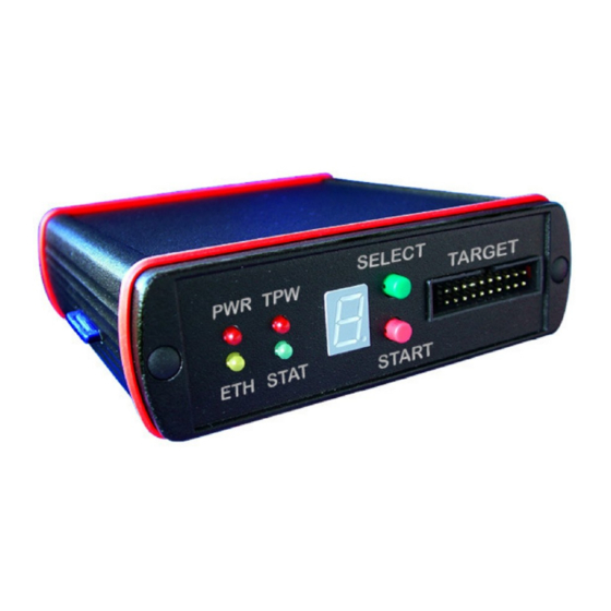
Page 136: Specifications
C . . . +60 Æ Æ Storage temperature C . . . +80 Relative humidity, non con- < 90% densing 4.1 JTAG Target connector signals Figure 18: Note: Each signal JTAG pin has a 10k pull-up. PEEDI User’s Manual www.ronetix.at... -
Page 137: Rs232 Connector (Db9F, Female)
JTAG Clock Output Connects to the target TCK line JTAG TDI Output Test Data In signal from PEEDI to the target JTAG port. Con- nects to the target TDI line. JTAG TMS Output Connects to the target TMS line. GDBRQ Output Controlled from a parameter in config file... -
Page 138: Schematics
Specifications RS232 connector pin configuration Description Not connected Not connected Ground Not connected Not connected 4.3 Schematics JTAG cable adapter schematics can be found here: http://download.ronetix.info/peedi/doc/schematics/ PEEDI User’s Manual www.ronetix.at... -
Page 139: Faq
$ arm-elf-insight myapp To connect to the target (assuming that your PEEDI is set to use IP 192.168.1.10) type in the console window: (gdb) target remote 192.168.1.10:2000 This will tell GDB to connect to PEEDI using remote protocol. Now you can load your application into targets... - Page 140 A: First restart PEEDI holding front panel buttons pressed, this way RedBoot will not execute its boot script and the main PEEDI application will not be loaded. Then you can access the command line via the RS232 port using suitable terminal application capable of opening the serial PC RS232 port or via telnet connecting to the port specified by the...
- Page 141 Q: How big image can PEEDI program? A: The image to program is not buffered to the PEEDI's RAM, but it is downloaded from a TFTP/FTP/HTTP server or a MMC/SD card and programmed in configurable data blocks (0.5-64KB). Which means, there is no theoretical maximum size limit of the image to be programmed.
-
Page 142: Glossary
- An executable file that has been loaded onto a processor for execu- tion. JTAG - Type of interface which enables direct access to most CPU re- sources. MMC/SD card - Multi Media or Secure Digital memory card, used to store files. PEEDI User’s Manual www.ronetix.at... - Page 143 RedBoot - The Red Hat boot loader used for update, setting some configuration parameters or to load and launch the PEEDI executable image. Script - List of CLI commands executed one by one until the last or until an error is returned.
-
Page 144: Peedi Package Contents
PEEDI Package contents 7 PEEDI Package contents Make sure all the items listed below are present, when opening the PEEDI package: - PEEDI - Power adapter 5V / 1A - JTAG or BDM cable and adapter - Patch cable CAT5, 2m - Serial cable, 1:1, 2m PEEDI User’s Manual... -
Page 145: Warranty
Warranty 8 Warranty RONETIX warrants PEEDI to be free of defects in materials and workmanship for a period of 36 months following the date of purchase when used under normal conditions. In the event of notification within the warranty period of defects in material or workmanship, RONETIX will replace defective PEEDI. -
Page 146: A Sample Target Configuration Files
Appendix A: Sample target configuration files A Sample target configuration files Please use this link to download the most recent version of the sample target configuration files: http://download.ronetix.info/peedi/cfg_examples PEEDI User’s Manual www.ronetix.at...
Need help?
Do you have a question about the PEEDI and is the answer not in the manual?
Questions and answers