Table of Contents
Advertisement
Quick Links
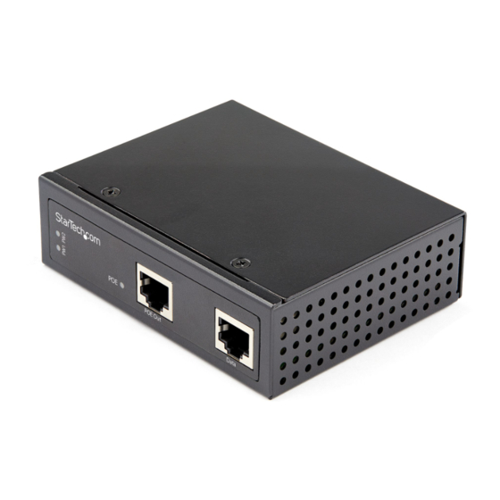
90W Industrial Grade Hardened 802.3bt PoE Injector | 1G (1000 Mbps)
Product Diagram (POEINJ1G90W)
1
2
3
Component
• Green: A Power Source is detected.
1
Power LEDs
• Off: A Power Source is not detected.
• Amber: Indicates that the PoE Injector is
2
PoE LED
• Off: Indicates that the PoE Injector is in idle
• Connect a Powered Device (PD) to the PoE
3
PoE Out Port
• Connect a Network Switch to the PoE
4
Data Port
4-Pin Terminal Block
• Connect an external DC Power Source (48-56V
5
V1 and V2
• Connect a ground connection to the Ground
6
Ground Screw
Requirements
For the latest requirements, please visit
• Small Flat Head Screwdriver x 1
• (Optional) Phillips® Head Screwdriver x 1
• (Optional) Writing Utensil x 1
• PoE Powered Device (PD) x 1
• Network Switch x 1
• DC Power Source or Universal Power Adapter with Type N (OD: 5.5 mm, ID: 2.5 mm)
Barrel Connector x 1
To view manuals, FAQs, videos, drivers, downloads, technical drawings, and more, visit www.startech.com/support.
4
5
Function
providing power.
mode.
Injector.
Injector.
DC Input) to the PoE Injector.
Screw when connecting a DC Power Source to
the PoE Injector.
www.startech.com/POEINJ1G90W
• RJ45 Terminated UTP/STP Cat 5e (or better) Network Cable x 2
Powering the PoE Injector
Terminal Block
Connecting and installing the 4-Wire Terminal Connector, must be completed by a
licensed Electrician.
Notes: Make sure that you turn off the power source before connecting the power wire
6
to the PoE Injector.
Do not exceed the recommend power source voltage as it may result in personal or
product damage.
1. Using a Small Flat Head Screwdriver, loosen the two screws (V1 or V2) on the
4-Wire Terminal Connector (included).
2. Connect the Power Wires from a DC Power Source (48 - 56V DC), or the provided
Barrel Power Connector Adapter, to the proper Terminal Block Connectors to
the terminals are marked on the PoE Injector's Casing. Connect the positive wire to
V+ and the negative wire to V-.
3. Tighten the two screws on the 4-Wire Terminal Connector.
4. Insert the 4-Wire Terminal Connector in the 4-Wire Terminal Block on the PoE
Injector.
5. To connect a second Power Source to the PoE Injector, repeat steps 1 - 4.
6. Using a Phillips Head Screwdriver, loosen the Ground Screw on the PoE Injector.
7. Connect the Ground Wire from a DC Power Source to the Ground Screw on the
PoE Injector.
8. Using the Phillips Head Screwdriver, tighten the Ground Screw to secure the
Grounding Wire to the PoE Injector.
(Optional) Barrel Connector
• Connect a Type N (OD: 5.5 mm, ID: 2.5 mm) Barrel Connector from a Universal
Power Adapter to the Terminal Block to Barrel Power Connector Adapter.
Connecting the PoE Injector
Notes: Make sure the total length of the CAT5e/6 Cable connecting the PD Device
to the PoE Injector and the CAT5e/6 Cable connecting the PoE Injector to the
Remote Switch does not exceed 100 meters in total length.
The PoE Injector is compatible with both Power over Ethernet (PoE) and 95W Power
over HDBaseT (PoH).
Quick-Start Guide
Manual Revision: June 2, 2020 11:37 AM
Advertisement
Table of Contents

Subscribe to Our Youtube Channel
Related Manuals for StarTech.com POEINJ1G90W


Summary of Contents for StarTech.com POEINJ1G90W
- Page 1 The PoE Injector is compatible with both Power over Ethernet (PoE) and 95W Power Barrel Connector x 1 over HDBaseT (PoH). To view manuals, FAQs, videos, drivers, downloads, technical drawings, and more, visit www.startech.com/support. Manual Revision: June 2, 2020 11:37 AM...
- Page 2 • Rör aldrig vid enheter med oskyddade kretskort när strömmen är påslagen. and do not represent an endorsement of a product or service by StarTech.com, or an endorsement of the product(s) to which this manual applies by the third-party company in question. StarTech.com hereby acknowledges that all trademarks, registered FR: startech.com/fr...
Need help?
Do you have a question about the POEINJ1G90W and is the answer not in the manual?
Questions and answers