Table of Contents
Advertisement
Quick Links
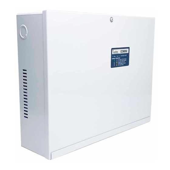
E3MINI Series
IMPORTANT SAFEGUARDS
When using electrical equipment, basic safety precautions should always be followed
including the following:
READ AND FOLLOW ALL SAFETY INSTRUCTIONS
A.
Do not use outdoors
B.
Do not mount near gas or electric heaters.
C.
Use caution when servicing batteries. Battery acid can cause burns to skin and
eyes. If acid is spilled on skin or in eyes, flush acid with fresh water and
contact a physician immediately.
D.
Equipment should be mounted in locations and at heights where it will not
readily be subjected to tampering by unauthorized personnel.
E.
The use of accessory equipment not recommended by the manufacturer may
cause an unsafe condition.
F.
Do not use this equipment for other than intended use.
This unit contains lethal voltages. There are no user serviceable parts inside. Only
authorized service personnel are to be used for service.
SAVE THESE INSTRUCTIONS
The installation and use of this product must comply with all national, state, municipal
or local codes that apply. Please read this manual thoroughly before installing and
operating the E3MINI Series central inverter system. For assistance please call ISOLITE
technical support at 800-967-5573 and speak to a technician during normal business
hours (EST).
Installation / Operation Manual
Emergency Lighting Central Inverter System
ISOLITE – THE EMERGENCY LIGHTING EXPERTS
31 Waterloo Avenue Berwyn, PA 19312 WWW.ISOLITE.COM
by
Advertisement
Table of Contents

Related Manuals for Isolite E3MINI Series


Summary of Contents for Isolite E3MINI Series
- Page 1 The installation and use of this product must comply with all national, state, municipal or local codes that apply. Please read this manual thoroughly before installing and operating the E3MINI Series central inverter system. For assistance please call ISOLITE technical support at 800-967-5573 and speak to a technician during normal business hours (EST).
-
Page 2: Table Of Contents
TABLE OF CONTENTS 1.0 Introduction 8.0 User Interface 1.1 Mechanical Design Features 8.1 LED1 – Charging Mode and Line 1.2 Electrical Design Features Status 8.2 LED2 – Inverter Mode and 2.0 Receiving and Storage Battery Level Indication 8.3 Minor Alarm 2.1 Inspection 8.4 Major Alarms 2.2 Storage... -
Page 3: Introduction
Normally-On and Normally- Off loads together causes less performance loss than traditional inverters. Since the active PWM regulation scheme produces a very low THD waveform, the E3MINI Series can power up even the most demanding loads driving its output with power factor capabilities ranging from 0.5 leading to 0.5 lagging. -
Page 4: Receiving And Storage
2.0 RECEIVING AND STORAGE 2.1 Inspection The E3MINI Series central inverter and batteries are shipped together. Upon arrival, please inspect the contents to ensure that no shipping damage has occurred. This is especially important with the batteries – ensure that there are no cracks or leaks. -
Page 5: Installation
LED status displays. 3.2 Operating Environment Choose a location that is controlled between 20 and 30 °C. E3MINI Series is UL listed between 20°C to 30°C (68°F to 86°F) because of battery discharge performance results. Do not install in a wet or damp location. Do not install in environments that will expose the unit to excessive temperatures like boiler rooms as this will significantly depreciate battery life. -
Page 6: Knockout Locations
3.4.3 Knockout Locations Electrical Knock Outs are provided on three surfaces of the E3MINI Series. Ensure all metal conduit is secured and tightened creating a good connection to earth ground. Use an Ohm-Meter to check that continuity between conduit and protective earth ground has been established. - Page 7 Knockout Locations – E3MINI Series 125W Knockout Locations – E3MINI Series 250W E3MINI SERIES | 7...
-
Page 8: Ac Connections
Series. Always keep Neutral and Ground wires separate and ensure no shorts occur. NOTE – Neutral (NEU) in the E3MINI Series is common to both the Input and Output. Never mix Neutrals for the building wiring (Non-Emergency) with the Emergency wiring. -
Page 9: Installing The Output Wires
Inverter mode of operation (Loss of utility power or system test). See section 9.4 thru 9.4.2 for additional details on load types. 4.3 AC Input(s) / Output(s) Diagram AC INPUT(S) AC OUTPUT(S) VOLTAGE SELECT JUMPER E3MINI SERIES | 9... -
Page 10: Battery And Dc Connections
E3MINI Series electronics module. See section 5.4 for detailed illustrations. DC Voltage of System The systems DC battery voltage for the E3MINI Series is 24VDC for both 125W and 250W models. This voltage is produced by connecting two 12V batteries in series for the 125W model and a series parallel connection for the 250W model. -
Page 11: Battery Wiring Diagrams
Battery Wiring Diagrams 125W Inverter – Single string of 24VDC Connect Jumper and wires as shown below 250W Inverter – Two strings of 24VDC Connect Jumpers and wires as shown below E3MINI SERIES | 11... -
Page 12: Startup And Shutdown Procedures
7.0 Specifications The E3MINI Series system can be overloaded during normal operation when the dimming option is used. The maximum allowable connected load for both the 125W and 250W model is 375W. The system must be tested to ensure that the connected load power does not exceed the systems rated power (125W/250W) while in the Inverter Mode of operation. -
Page 13: Specifications
0 to 40 °C (Batteries) Relative Humidity <95 % (non-condensing) Physical Cabinet NEMA Type 1 enclosure, 16 AWG powder painted CRS Cooling Natural Convection – No fans Size/Weight 15.4W-12H-4.25D / 33lbs. (125W Model) 15.4W-17.3H-4.25D / 57 lbs. (250W Model) E3MINI SERIES | 13... -
Page 14: User Interface
8.0 USER INTERFACE There are two heads-up LEDs to indicate system status and a recessed test button to initiate the inverter to run in Inverter Mode. Both LED1 and LED2 are bi-color LED’s and will illuminate either solid, blinking, or change between colors for different modes of operation or faults. -
Page 15: Startup Faults
BACKFEED (LED1/LED2 – 7 Blinks) Indicates that there is an AC voltage back-feeding the output terminals. This fault means that the E3MINI Series was wired incorrectly between the output terminal and the load(s). 8.6 Charger Faults: While the batteries are being charged, the system will continuously check for faults as part of its diagnostic capabilities. -
Page 16: Inverter Faults
Indicates that there is AC voltage already at the output terminals back-feeding into it. This fault means that the E3MINI Series was wired incorrectly between the output terminal and the load. Since this fault was already checked at power up, it is possible that there is a remote transfer device which is back-feeding during Inverter operation. -
Page 17: System Operation
9.0 SYSTEM OPERATION 9.1 Startup Mode When the E3MINI Series is first turned on using the System ON/OFF switch, it goes through a sequence of self-tests which ensures proper connections are made and it also checks for faults that may be present. The inverter must qualify several things before advancing to the Battery Charging mode. -
Page 18: Inverter (Batter Discharge) Mode
Since the crest factor is very high on the E3MINI Series, loads that have high inrush currents are quickly up and running. This is very beneficial with Switched or Normally- Off loads. -
Page 19: Warranty
10.0 WARRANTY There are two separate warranty periods for the E3MINI Series Central Inverter System. The Electronics/Cabinet warranty period is for 3 years from the date of shipment. It is warranted against defects in workmanship and materials under normal and proper use. -
Page 20: Maintenance And Service
Please refer to Start up and Shut Down procedures for details. CAUTION – Always assume AC and DC Voltages are present at the E3MINI Series terminals because the inverter is capable of providing output voltage from the batteries when there is no AC input. -
Page 21: Battery Replacement
11.2 Battery Replacement E3MINI Series is a UL approved and listed component with exact battery requirements. Failure to replace the batteries with the exact same type will VOID the UL approval. For battery replacement, please call the service number listed in the warranty section so that the unit performs as it was intended. -
Page 22: Fire Alarm/Dimming Option
DIMMABLE EMERGENCY FIXTURE’S LED driver will transfer to the USER PRESET levels. 12.2 Operation The Dimming Module provides 3 independent channels of 0-10V/DALI control signals for use in Emergency Lighting. A simplified block diagram of one channel is as follows: E3MINI Series DIMMABLE DIMMER MODULE DIMMER CONNECT... -
Page 23: User Presets
USER PRESET value. This is very helpful to adjust the DIM1-3 signal and check for illumination and power consumption levels. Dimming Board V/I Relation Position1 Position2 Position3 Position4 Position5 Current (mA) E3MINI SERIES | 23... -
Page 24: Fire Alarm/Dimming Connections
DALI interface requires the DIM ADJ. to be in the furthest Clockwise (CW) so that the relay opens during Inverter Mode of operation. Dimming requires a DALI signal which the E3MINI Series does not provide. 24 | INSTALLATION / OPERATION MANUAL... - Page 25 E3MINI SERIES | 25...
- Page 26 26 | INSTALLATION / OPERATION MANUAL...
-
Page 27: Testing The Dimmer Option
Emergency Lights. The Emergency Lights will go to full brightness or to a preset level adjusted internally in the Inverter. AC Output OUT 1 is energized regardless of the state of the CMD 1. E3MINI SERIES | 27... -
Page 28: Typical Wiring Diagrams
13.0 Typical Wiring Diagrams DIAGRAM #1 Input Power LINE Earth GND N-ON Operation: Normally-On output is ALWAYS energized 24/7. Use this output when you need a continuous un- interrupted source of power. Note: LED Fixture Neutral wire not shown. LED Fixture Always run dedicated hot and neutral wires to emergency fixtures per NEC code. - Page 29 LED Fixture LED Fixture Neutral wire not shown. Always run dedicated hot and neutral wires to emergency fixtures per NEC code. Wiring Diagram Using Normally-Off Outputs Use when Lights are energized ONLY during Inverter Mode of operation E3MINI SERIES | 29...
- Page 30 DIAGRAM #3 Input Power LINE Earth GND CMD 1 CMD 2 OUT 1 -OR- OUT 2 CMD 3 -OR- OUT 3 Switch Device LED Fixture (NO DIMMERS) Operation: Use Switched Command(s) CMD 1, CMD 2, or CMD 3 Note: to energize lights connected on OUT 1, LED Fixture Neutral wire not shown.
- Page 31 Always run dedicated hot and neutral wires to emergency fixtures per NEC code. Wiring Diagram Using Line Voltage Dimming Use when line dimming from Normally-On and bypass with OUT 1, OUT 2 or OUT 3 during Inverter Mode E3MINI SERIES | 31...
- Page 32 DIAGRAM #5 Input LINE Power CMD 2 Switch for ZONE 2 CMD 1 OUT 3 OUT 2 OUT 1 N-ON Switch for Zone 1 Lights ZONE 3 Operation: Zone 2 Lights Use any of the outputs configured for your application. Zone 1: Normally-On night lights Zone 3 Lights Zone 2: OUT 1 switched On/Off...
Need help?
Do you have a question about the E3MINI Series and is the answer not in the manual?
Questions and answers