Table of Contents
Advertisement
Installation/Operation Manual for E3-MAC Emergency Lighting Central Inverter System
IMPORTANT SAFEGAURDS
When using electrical equipment, basic safety precautions should always be followed including the
following:
READ AND FOLLOW ALL SAFETY INSTRUCTIONS
A. Do not use outdoors
B. Do not mount near gas or electric heaters.
C. Use Caution when servicing batteries. Battery acid can cause burns to skin and eyes. If acid is
spilled on skin or in eyes, flush acid with fresh water and contact a physician immediately.
D. Equipment should be mounted in locations and at heights where it will not readily be subjected
to tampering by unauthorized personnel.
E. The use of accessory equipment not recommended by the manufacturer may cause an unsafe
condition.
F. Do not use this equipment for other than intended use
This unit contains lethal voltages. There are no user serviceable parts inside. Only authorized service
personnel are to be used for service.
SAVE THESE INSTRUCTIONS
The installation and use of this product must comply with all national, federal, state, municipal or local
codes that apply. Please read this manual thoroughly before installing and operating this Central
Inverter System. For assistance please call Technical Service at 800-967-5573 and speak to a technician
during normal business hours (EST).
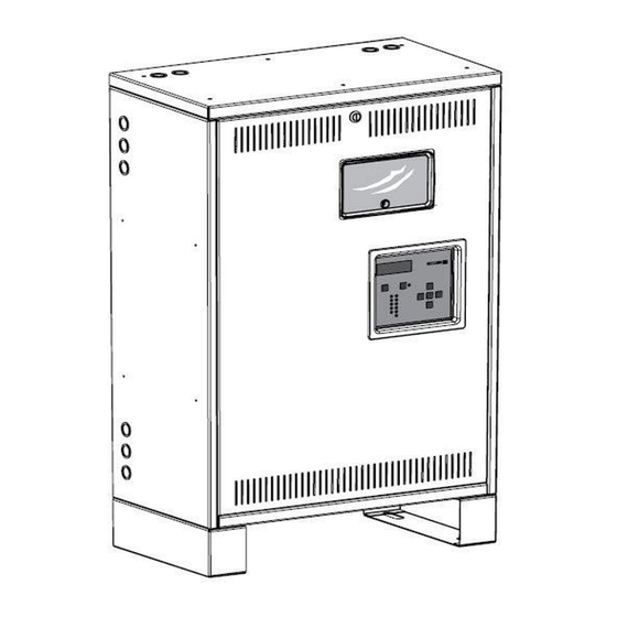
E3-MAC Series by Isolite
1.0KW – 3.0KW Models
1KW Model – Single Cabinet
1
Advertisement
Table of Contents

Subscribe to Our Youtube Channel
Related Manuals for Isolite E3-MAC Series


Summary of Contents for Isolite E3-MAC Series
-
Page 1: Save These Instructions
E3-MAC Series by Isolite Installation/Operation Manual for E3-MAC Emergency Lighting Central Inverter System 1.0KW – 3.0KW Models 1KW Model – Single Cabinet IMPORTANT SAFEGAURDS When using electrical equipment, basic safety precautions should always be followed including the following: READ AND FOLLOW ALL SAFETY INSTRUCTIONS A. -
Page 2: Table Of Contents
Table of Contents Introduction Mechanical Electrical Receiving and Storage Inspection Storage Installation Location Operating Environment Ventilation Mounting Guidelines 3.4.1 Clearance 3.4.2 Floor Preparation 3.4.3 Knockout Locations AC Connections Removing the Front Cover Removing the AC Breaker Cover Installing the Input Wires Installing the Output Wires Battery and DC Connection Battery Inspection... - Page 3 8.8.8 Utility Failure Alarm 8.8.9 High Temperature Alarm 8.8.10 Time Delay 8.8.11 Load Reduction 8.8.12 Relay 1 8.8.13 Relay 2 8.8.14 Backup Logs 8.8.15 Contact Name 8.8.16 Contact Phone Factory Setup 8.10 System Info System Operation Start-Up Mode Battery Charging Mode Switched Output Inverter Power Mode 10.0...
-
Page 4: Introduction
Introduction This Central Inverter System integrates the latest power electronics and microprocessor technology which produces a pure sine wave power output intended for use in Emergency Lighting. The system is very efficient on-line and typically has a standby power loss of only 2 percent of the systems total capacity which means it is 98% efficient. - Page 5 The Inverter utilizes a bi-directional converter that is either MOSFET or IGBT technology based on the DC voltage of the system. The system does not require installers to go through a manual pre-charge and dis- charge procedure to start the system up because these components are built into the Inverter Modules. The overload capabilities of the system defined by its crest factor (minimum of 4.0) which means that universal ballasts and drivers present no issue starting up on Inverter Power and it can sustain a minimum of 400 percent for about a half second.
-
Page 6: Receiving And Storage
Receiving and Storage Inspection The Cabinets and Batteries may be shipped on the same pallet or may be shipped separately. Upon arrival please inspect the contents to ensure that no shipping damage has occurred. This is especially important with the batteries – ensure that there are no cracks or leaks. If any damage has occurred notify the shipping carrier immediately and submit a damage claim. -
Page 7: Installation
Installation Location NEC article 700 EMERGENCY CIRCUITS should be referenced for proper installation of a Central Inverter System. Article 700 dictates that unit must be mounted in a permanent location. Choose a cool dry place with normal ventilation and one which will allow easy access for testing and maintenance. Avoid a location which could allow vandalism and tampering with. - Page 8 Figure 1 – Overall Dimensions Diagram shows both side by side and top and bottom mounting configuration. Top and Bottom mounting configuration is factory preferred for control panel access. Battery Cables from Factory are sized for top and bottom mounting configurations.
-
Page 9: Knockout Locations
3.4.3 Knockout Locations EKO’s (Electrical Knock Outs) are provided on the Left side, Right side and also the Top side surfaces. Ensure all metal conduit is secured and tightened creating a good connection to earth ground. Use an Ohm-Meter to check that continuity between conduit and protective earth ground has been established. -
Page 10: Ac Connections
AC Connections WARNING – Only qualified personnel that are familiar with AC and DC installation techniques and codes (such as an electrician) should perform the Installation. WARNING – This system contains lethal AC Voltages. Because of these hazards of high voltage electrocution, always shut down all sources of power before you install, maintain, or service the unit. -
Page 11: Removing The Ac Breaker Cover
Removing the AC Breaker cover To access wiring to the breakers, remove the two ¼-20 screws from the plastic breaker cover with a 3/8 socket or nut driver and the circuit breakers cover will easily remove. This cover conceals the wiring area and also provides a safety barrier so that fingers cannot inadvertently touch live parts after installation. -
Page 12: Installing The Output Wires
Installing the Output Wires Connect the load wires to the provided terminal block labeled N. On. If switched loads were installed from the factory, connect the switched loads to the breakers to the right of the input breaker. There are dedicated neutral and ground blocks which should be shared for the AC input and AC output. -
Page 13: Battery And Dc Connection
Battery and DC Connections WARNING – Only qualified personnel that are familiar with AC and DC installation techniques and codes (such as an electrician) should perform the Installation. WARNING – Remove all rings, watches, and other jewelry before doing any electrical service or installation work. - Page 14 Figure 5– 1KW / 48VDC Diagram Figure 6 – 2.2KW / 96VDC Diagram...
- Page 15 Figure 7 – 2.8KW / 120VDC Diagram Figure 8 – 3.0KW / 48VDC Diagram...
- Page 16 Figure 9 – Optional Seismic Restraints Illustration...
-
Page 17: Start Up And Shut Down Procedures
Start up and shut down procedures Start-Up After the AC input and output wires are connected and the batteries are properly installed, the unit is ready to be started up. Start-up requires that the AC input be present. The unit will not start up without AC input voltage. -
Page 18: 7.0 Specifications
7.0 Specifications Input Voltage Model and Voltage Dependent (see chart 7.1) Current Model and Voltage Dependent (see chart 7.1) Frequency 60Hz +/- 2 Hz Protection Input Circuit breaker with fast acting semiconductor fuse in series for Selective Coordination and improved KAIC withstand Power Factor 0.5 lead to 0.5 lag Output... -
Page 19: Input / Output Voltage And Current Chart/Matrix
Product Line Voltage Current Chart/Matrix Module Module Input/Output Input Output Battery Battery VA Output Size Voltage Current Current Voltage Current 1000 10.5 23.5 1000 23.5 1000 1000 23.5 1000 23.5 1000 23.5 2200 22.9 18.3 24.9 1100 13.2 10.6 50.9 2200 2200 11.5... -
Page 20: Mmi (Man Machine Interface)
Man Machine Interface (MMI) Introduction: The Man Machine Interface (MMI) or Front Panel consists of a 5 button keypad (Left Key, Up Key, Right Key, Down Key and Enter Key) for menu navigation, a 4x20 character backlit White LCD display, Heads- Up LEDs for quick diagnosis of system status and alarms, Dedicated System Test pushbutton and Alarm Silence On/Off pushbutton. -
Page 21: Keypad And Display
During a System Test and also during a power outage when the system is on Inverter Power, the audible alarm will beep momentarily once every second. 8.1.3 Keypad and Display Features: Using the Keypad and 4x20 Display, the user can access all features of the system including Meter Measurements, User Settings, Test Logs, Alarm Logs, Event Logs, System Info, Alarms and System Info. -
Page 22: Event Log
Fixed alarms are not user adjustable nor can they be turned on or off – they are always active and are imperative for proper safeguarding and operation of the system. The factory has broken down these alarms into three modes of operation which are Startup, Charger and Inverter modes. The possible fixed alarms are Startup Alarms (Communication, Setup Conflict, Battery Voltage, Back-Feed, Transfer /AC Fuse, Overload, Mis-Wire, Incorrect AC), Charger Alarms (Communication, Over-Temperature, DC Fuse, No Charge, Overcharge, Back-Feed, AC Fuse/Wiring, Program Reference), Inverter Alarms... -
Page 23: User Menu
User Menu: From the Scrolling Home Pages, press Enter Key and down arrow to select User Menu and press Enter to get to the password entry screen. The User Password is 4 keystrokes - Left Key, Right Key, Left Key, and Right Key. -
Page 24: High Temperature Alarm
8.8.9 High Temperature Alarm – The system has an internal temperature sensor so the system temperature may be a bit higher than ambient temperature – please keep this in mind if using the High Temperature Alarm. The High Temperature alarm is adjustable from 0 °C - 60 °C and is activated when the temperature goes above this level. -
Page 25: Factory Setup
When the correct number or letter is reached, scroll left or right for the next character or press Enter when finished. Factory Setup: This menu is not available to Users and is reserved for qualified field technicians and Factory Representatives. 8.10 System Info: The System info displays the software revision of the MMI and the Controller IO on the first screen. -
Page 26: Battery Charging Mode
INCORRECT AC – The wrong voltage is being applied to the system After all the Start-Up diagnostics are performed, the system is OK to proceed to the Battery Charging mode. Battery Charging Mode The Battery Charging mode is where the system will remain for 99.9+ percent of its life. In this mode, AC power is being passed through to the units output and subsequently its loads and the batteries are keeping a float charge. -
Page 27: Inverter Power Mode
The Switched output can be energized while in the Battery Charging mode of operation by applying 120 or 277 VAC to the Switched Enable Input. When this system changes mode of operation to the Battery Power mode, the Switched Output will automatically energize. -
Page 28: Warranty
10.0 Warranty There are two separate warranty periods for this Central Inverter System. The Electronics/Cabinet warranty period is for 3 years from the date of shipment. It is warranted against defects in workmanship and materials under normal and proper use. The batteries are covered under a separate warranty and these durations may change dependent on battery type. -
Page 29: Maintenance And Service
11.0 Maintenance and Service CAUTION – Whenever maintenance and service is to be performed, it may be desirable to shut unit down. Please refer to Start up and Shut Down procedures for details. CAUTION – Always assume AC and DC Voltages are present at the output terminals because the system is capable of providing output voltage from the batteries when there is no AC input. -
Page 30: Battery Maintenance
11.1 Battery Maintenance The batteries used in this system are sealed lead calcium and are termed “Maintenance Free”. This term may be misleading because ALL batteries require periodic maintenance even if it only consists of a visual inspection. We recommend the following maintenance plan: ... -
Page 31: Web Interface
To remove the batteries, shut the unit completely down by turning off the System On/Off switch and remove AC power Feed source by turning off the input circuit breaker. Disconnect the battery inter-connect jumpers and the wires for inter-shelf connection if present. After all wires are disconnected, simply slide the batteries forward for removal. -
Page 32: User Setup
Meter Functions – Input Voltage, Output Voltage, Output Current, Output VA, System Battery Voltage, Battery Current (charging and discharging), Battery Power, System Temperature, System Days, Inverter Minutes and System Events. Also included in the Control Panel is the System Status and include indicators for Battery Charging, Inverter Power On, AC Present, System Ready, and Switched Load Energized. -
Page 33: Charts And Graphs
Phase Rotation, Circuit Breaker Trip, Unit in Bypass, Inrush Alarm, Low Battery, Near Low Battery, High Temperature, Overload, Overload Shutdown, Utility Failure, Low VAC, High VAC, Load Reduction 12.5 Charts and Graphs Page(s): Since all critical data is taken every second from the inverter, real-time information such as Meter and Status and Alarms are all live 24-7. -
Page 34: 12.5.6 Discharge Power
12.5.6 Discharge Power: Graphed in VA Output for the user selected time period. Similar to Output VA such that Minimum and Maximum values of Output VA can be selected/un-selected and cause the graph to show both simultaneously or one at a time. The graph can be scaled to Days (30) by choosing the Month, or Hours (24) by choosing the Date.
Need help?
Do you have a question about the E3-MAC Series and is the answer not in the manual?
Questions and answers