Table of Contents
Advertisement
Advertisement
Table of Contents

Related Manuals for STONEX X300


Summary of Contents for STONEX X300
- Page 1 X300 TONEX User Manual __________________________________________________________________ Revision 12 September 2016 STONEX® Srl | Via Cimabue 39 | 20851 - Lissone (MB) | Italy Phone +390392783008 ; +390392785575 | Fax +390392789576 | www.stonexpositioning.com...
-
Page 3: Table Of Contents
Contents COMPANY INFO ..........................1 LEGAL NOTICE ............................ 1 COPYRIGHTS AND TRADEMARKS ....................... 1 RELEASE NOTICE ..........................1 STANDARD LIMITED WARRANTY ......................1 GENERAL WARRANTY FOR INSTRUMENTS ..................1 SHIPPING POLICY ..........................2 RETURN POLICY DEAD ON ARRIVAL INSTRUMENTS ................2 FIRMWARE/SOFTWARE WARRANTY .................... - Page 4 1.12 ABOUT USER ........................14 1.13 EXCEPTIONS FROM RESPONSIBILITY..................14 CHAPTER 2: SETTING UP THE STONEX X300 ..................15 2.1 SETTING UP ..........................15 2.2 INSERT/REMOVE THE BATTERY ....................16 2.2.1 PLUG THE X300 BATTERY ....................16 2.2.2 REMOVE THE X300 BATTERY .................... 17 2.3 CHARGE THE BATTERY ........................
- Page 5 3.5.9.7 AUTOMATIC SHUTDOWN ..................61 X300 L - PAY PER USE ......................62 3.6.1 UPLOAD THE “PAY PER USE” FIRMWARE ................. 63 CHAPTER 4: MANAGE DATA WITH STONEX RECONSTRUCTOR SOFTWARE ........64 X300 FILES FORMAT ......................64 FILE SIZE ..........................65...
- Page 6 4.3.1 GENERAL IMPORT AND EXPORT FORMATS (V.3.2) ............66 4.3.2 X300 MANAGER: CONVERT X3R, X3I AND X3A FILES ............67 4.3.3 IMPORT AND COLOR THE X300 POINT CLOUDS ............... 69 4.3.4 IMPORT THE X300 MULTIPLE-SCAN POINT CLOUDS ............72...
-
Page 7: Company Info
STONEX® agree to repair or replace the defected instrument within thirty (30) days, only if STONEX® recognizes that the defects of the instrument are not caused by human factors or no obvious damage to its surface is visible. STONEX® warrants any new replaced parts or... -
Page 8: Shipping Policy
NOTE: STONEX® is not accountable for the unlikely event that the Products get lost in transit. Any damage inflicted by the customer or by third party after the products have been delivered... -
Page 9: Disclaimer And Limitation Of Remedy
If dealer wants to repair an instrument under warranty period on their site: 2.1 If dealers don’t have the part in stock they have to send an official order to STONEX® and pay for it and then so STONEX® will send the new part to them so they can repair the instrument. -
Page 10: Environmental Recycling
If the instrument needs to be sent back to STONEX® for repair/replacement, dealers/customers have to send to STONEX® a “Returned Merchandise Authorization (RMA)” before they send back the fault instrument. STONEX® shall, at its sole discretion, decide on the place of performance for work under warranty. -
Page 11: Chapter 1: Introduction
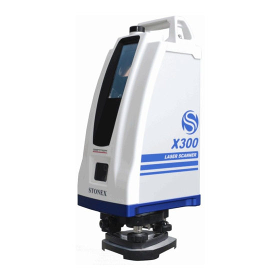
Chapter 1: Introduction 1.1 General STONEX® is the manufacturer of the 3D Laser Scanning System STONEX X300. Laser scanning is an automatic process during which real objects are surveyed and sampled almost completely to determine their location, size, orientation and form. The STONEX X300 rapidly determines high-resolution measurement results within very short time and within a field of view of max. -
Page 12: Description Of The System
1.3 Description of the system Transport handle GPS mount (standard 5/8” fitting) Laser window Camera window (Camera UP and Camera DOWN) Figure 2: X300 Rear side Figure 1: X300 Front-Right side Power button Led control bar USB port Smart port: Ethernet and external... -
Page 13: Operational Specifications
1.4 Operational specifications X300 supports four scan modes at different resolution (point grid). Scan time varies according to the scan mode. H. step (‘) V. step (‘) Resolution H. res. (360°) V. res. (90°) Total points Time x 360° * Columns/sec. -
Page 14: Precautions For Safety
When the instrument is working it is normal if you hear noises from instrument motors. They will not affect the instrument work. ◆ Stored data responsibility STONEX® should not be held liable for the lost data because of wrong operation. -
Page 15: Transport And Shipping
Always carry the product in its transport container and secure it. ◆ Shipping When transporting the product by rail, air or sea, always use the complete original STONEX® packaging, transport container and cardboard box or its equivalent to protect the instrument against shock and vibration. -
Page 16: Cleaning And Drying
Do not put the battery in the fire or high temperature condition. Explosion, damage could result. Do not use the battery which is not specified by STONEX®. Fire, electric shock or burn could result. Do not use the power cable which is not specified by STONEX®. Fire could result. -
Page 17: Safety Standards For Laser
USB port in safe environment, in order to avoid harming the device. 1.10 Safety Standards for Laser STONEX X300 series adopt the class of Laser Product according to IEC Standard Publication 60825-1 Amd. 2:2001. According this standard, EDM device is classified as Class 1M Laser Product. -
Page 18: Battery Specifications
1.11 Battery Specifications 1.11.1 Components Information Product: Lithium battery Product Type: Lithium Polymer Battery Energy: less than 100 W/h each cell Nominal Voltage: 3.7 Volt Product composition Content (%) Rare earths >40 (No metal Lithium at all) >10 >2.0 >0.1 Graphite >2.0 >0.1... -
Page 19: Temperature Range
1.11.7 Toxological information STONEX® Lithium-Ion rechargeable batteries do not contain toxic materials. 1.11.8 Ecological information When properly used or disposed, STONEX® Lithium-Ion rechargeable batteries can be recycled and do not present environmental hazard during their life time. 1.11.9 Disposal considerations Dispose in accordance with applicable regulations, which vary from country to country. -
Page 20: About User
1.12 About User This product is for professional use only! The user is required to be a qualified surveyor or have a good knowledge of surveying, in order to understand the user manual and safety instructions, before operating, inspecting or adjusting. Wear required protectors (safety shoes, helmet, etc.) when operating. -
Page 21: Chapter 2: Setting Up The Stonex X300
Chapter 2: Setting up the STONEX X300 2.1 Setting up Extend the tripod legs to the same length to allow for a comfortable working posture. Tighten the screws at the bottom of the legs. Fold the handles down to detain the length of the legs. -
Page 22: Insert/Remove The Battery
Figure 3 represents the X300 battery pack: for proper mounting, the connectors must be facing up and the handle must be on the outer side. Figure 4 represents the X300 battery housing, placed in the rear side of the scanner. Figure 3: X300 battery pack Figure 4: X300 battery housing 2.2.1 Plug the X300 Battery... -
Page 23: Remove The X300 Battery
Figure 7: Unplug the battery pack Figure 8: Unplug the battery pack 2.3 Charge the battery The X300 battery can be charged directly using the appropriate battery charger, included in the bundle (Figure 10). Power specifications: Figure 10: Battery charger... -
Page 24: Features
2.3.1 Features Model: Li-ion battery charger Input: AC 100 ~ 240 V 50/60 Hz Output: 12.6 V / 3 A 2.3.2 Battery Charge Connect the AC cable to the power pack as described in Figure 11. Plug the power connector to the battery as described in Figure 12. Connect the external power unit to the power source. -
Page 25: Chapter 3: Operating The Stonex X300
The following workflow describes the operations performed during the power on process. To power on the X300 simply press the power button on the top of the instrument. There’s no need to press and hold the button: just push and release it. -
Page 26: Power Off The Scanner
3.2 Power off the scanner There are two ways to power off the X300 laser scanner. 3.2.1 Standard power off 3.2.1.1 Up to firmware version 0.4.100 Push and hold the power button After a while a beep will be emitted, continue to press the button A second beep will be emitted, continue to press the button After a while, a series of beeps will be emitted. -
Page 27: Led Indicators
3.3 Led indicators There are 14 LED indicators placed on the top of the instrument. Three LEDs on the left margin are dedicated to the X300 status. They are in different colors. Starting from the left: Red, Yellow, Green... -
Page 28: Status Leds
The system is ready and waiting for user input System error. Use the controller to check the failure on Status section. Scan initialization X300 is busy working on something (performing a scan, for example) X300 is storing data Scan successfully completed A new system controller firmware is uploading An indeterminate state. -
Page 29: Gps Leds
When a supported and configured receiver is connected to the X300 with X300 GPS kit accessory, the scanner is able to track the position of the receiver. The GPS coordinates are automatically stored in the scanner raw data and will be used by Stonex Reconstructor software to geolocalize the scanner position. -
Page 30: Stonex Gps Kit
5/8” fitting, then connect it using the GPS kit serial cable: - The cable end with the 7-pin connector goes to the GNSS receiver (bottom plate); The cable end with the 5-pin circular connector goes to the GPS port of the X300 laser scanner (see par. 1.3);... -
Page 31: Compatibility With Third-Party Gnss Receivers
3. Turn on the X300 laser scanner, wait for the initialization and check the satellites and the status by looking at the GPS led section on the right margin of the X300 LED bar (see par. 3.3 and par. 3.3.2). -
Page 32: Battery Level Alert
3.3.3 Battery level alert The battery level is continuously monitored. The critical threshold is below 20% and the alarm is visible on the RED Status LED: At 20% : LED is on, with 1 second off every 8 seconds At 15% : LED is on, with 1 second off every 2 seconds ... -
Page 33: Gps Offsets
3.3.5 GPS offsets The following diagram shows the position of the origin point of the measures and the relative offsets to the GPS mount. Figure 16: GPS offsets... -
Page 34: X300 Framework Offsets (Optional Accessory)
3.3.6 X300 Framework offsets (optional accessory) X300 Framework is compatible only with X300 laser scanners of the “PS4” serie. Control the scanner S/N to check the serie number. Example: X300PS4XXXXX Figure 17: X300 Framework offsets... -
Page 35: Use Of The Onboard Software
3.4.1 Tested OS and web browsers The X300 web interface is based on HTML 5 markup language and it is compatible with most of the latest browsers on the market. The table 6 reports the operating systems and web browsers that have been successfully tested with X300 web interface. - Page 36 (e.g: X300-DEMO-26) Connect to the X300 network. It is an open connection, no passkey is required. Open the web browser: the X300 main page will appear.
- Page 37 If not, refresh the page or enter the following IP address: 192.168.1.11 The access to the main page is protected by User ID and Password. Default settings: User ID: x300 or X300 (no case sensitive) Password: 1234 Users can later chose whether to change user ID and password or remove the protection.
-
Page 38: Web Interface
3.5 Web interface 3.5.1 Home page The Homepage is the main menu of the X300 web interface. From here users can access to all the X300 functions and settings. Homepage Functions Simple scan Enter the single scan procedure Multiple scan... -
Page 39: Simple Scan
3. Horizontal angle Set the angle for the horizontal rotation of the scanner (unit: °deg). 4. Starting Position of Scan Set the starting position of Laser X300 (Index or Actual Position) 5. Photos Enable/Disable the photos capture using the X300 internal cameras. - Page 40 Renaming the new scan, if the scan file already exist in the Files management archive or the file name is invalid, the scan name will be colored in red and a message with a suggested name will appear in a yellow box. Click on it to accept the suggestion.
- Page 41 3. Scan Scanning in progress. Use either the software progress bar on the control device or the LEDs status bar on the X300 to check the progress. When the scan is finished, the X300 will return to the origin position.
-
Page 42: Multiple Scan
3.5.3 Multiple scan Multiple-scan function is available from v. 08.00 of the X300 firmware (October 2015). The Multiple-scan menu allows to perform sequencial sub-scans of specific areas by manually selecting rectangular frames on a main preview grid, used as reference. - Page 43 3. Scan Scanning in progress. Use either the software progress bar on the control device or the LEDs status bar on the X300 to check the progress. When the scan is finished, the X300 will return to the origin position.
- Page 44 7. Photos Enable/Disable the photos capture using the X300 internal cameras. When the control is enabled, the X300 automatically takes the pictures after scanning. The two synchronized onboard cameras allow to cover the vertical angle of the scan. The number of the pictures varies according to the the width of the horizontal angle.
- Page 45 At the end of each scan the X300 will return to the homing position and then move to the next scan-frame, according to the following cycle: Scan 1/n Home Scan 2/n Home Scan 3/n Home …. Scan n/n Home ...
-
Page 46: Single Point Measure
It is also possible to measure the distance between two selected points within the same point cloud (par. 3.5.5). The single point measure is available for all the X300 scan modes, with the following constraints: Scan resolution Max H. angle Preview 360°... - Page 47 When the high-quality preview is displayed, it is possible to slide the image from right to left and vice versa using the cursor (pc) or fingers (touchscreen) 2. Select the point to measure Select the point on the preview using the finger (touchscreen) or the mouse (pc).
- Page 48 Tap the Store point button to save the point and add it to the point list. The measure is stored in the X300 internal memory and it is linked to the point cloud, so that the points are reloaded and displayed each time that the scan file is opened in the File Management menu.
- Page 49 5. Download the points file It is possible to download the points file in ASCII .txt format from the File Management menu (par. 3.5.6). Open the scan file to which le points file is linked an press the Point distance and coordinates (TXT) button.
-
Page 50: Measure The Distance Between 2 Points
Distance between 2 points Functions The single point measure function is available in the Files Management menu (par. 3.5.6) for every scan file stored in the X300 internal memory. 1. Get single point menu Press the Point button to enter the Single point measure menu. - Page 51 Tap the Store point button to save the point and add it to the point list. The measure is stored in the X300 internal memory and it is linked to the point cloud, so that the points are reloaded and displayed each time that the scan file is opened in the File Management menu.
- Page 52 Press the Delete all points button to permanentry erase all the points from the point list and from the X300 internal memory. 5. Select point 1 and point 2 from the point list Select the first point from the point list by tapping on it. The image coordinates are displayed in the boxes below.
-
Page 53: Files Management
3.5.6 Files management Files management Functions From this menu it is possible to browse the files stored in the internal memory, manage them and find out scan information. Giving a quick look at the page, you can receive direct information: ... - Page 54 Firmware versions later than 0.5.48 enable an integrity test function on the USB memory drive: Test USB dongle (see par. 3.5.9.6) NOTE Plug the USB memory drive in the X300 USB port only after powering on the scanner and remove it after turning off the scanner.
- Page 55 Download of the selected file through Wi-Fi or Ethernet cable (optional). On the right there is the estimated file size. d. Manage - Delete Erase the selected file from X300 internal memory. NOTE Deleted files are permanently removed from the X300 solid memory.
-
Page 56: Camera
3.5.7 Camera Camera Functions From this menu it is possible to check the light exposure of the digital cameras and take a shot to check it on camera up and down separately. Auto exposure Flag this checkbox to activate the light auto- exposure for each picture of the scan session. -
Page 57: Preferences
tracking light (not for measures) Upgrade firmware: enter the menu for the upgrade of the X300 internal firmware (see par. 3.5.8.4) 3.5.8.1 Language Language Functions From this menu it is possible to change the default language of the X300 onboard software. -
Page 58: Security
Press Update button to apply the changes. 3.5.8.3 Compensator Calibration/Compensator Functions In this menu it is possible to check if the X300 Laser Scanner is leveled and if the internal compensator of the X300 is correctly set. It’s important to verify if the compensator is properly calibrated or not. - Page 59 The compensator operative range is ± 20°. Wider tilt angles cannot be measured and adjusted. As consequence, the scan position in Stonex Reconstructor will result incongruous with respect to the main XYZ axis orientation. Beside this, no deformation is applied to the...
-
Page 60: Home Position Management
3.5.8.4 Home position management Home position managment Functions In this menu it is possible to set the X300 Laser Scanner home position choosing if: Maintain the factory home position Move to a specific angle (it isn’t possible to set a negative value) and set it as “new user home position”... -
Page 61: Upgrade Firmware
The need to update the firmware may have several reasons: release of new functions, bug fixing and improvements of existing software features. Firmware update can be carried out either by Stonex authorized dealers and end users. If you need further instructions or have questions about the procedure, please contact the Stonex LaserTeam support at: Laser.Team@stonex.it... - Page 62 YELLOW: the firmware is less recent than the currently installed one. NOTE It is possible to upload several firmware on the same scanner, the files will be visible in the X300 firmware list, but firmwares are upgradable only one-by-one. Step 4...
- Page 63 Wait until the end of the upgrade procedure. It takes less than a minute to complete the process. When the procedure is complete, the X300 will automatically restart and the firmware will be automatically deleted from the internal memory of the instrument.
-
Page 64: Information
Tools Specific technical tools: Download X3K (see par. 3.5.9.5) Download User Guide Tap on it to download the X300 User Guide in .PDF format. Upgrade firmware (see par. 3.5.8.4) Test USB dongle (see par. 3.5.9.6) ... -
Page 65: X300 Status
The components that are working properly are marked with the initials “OK”. If the Status is other than “Ready”, please contact Stonex Laser Team support at Laser.Team@stonex.it , providing the .X3K file (see par. 3.5.9.5) 3.5.9.2 System... -
Page 66: Internal Memory
From this menu users are allowed to easely verify which functionalities of the instrument are enabled or locked, according to the purchase agreement. In Device section, you can see the serial number and the X300 ID, which identify uniquely the single instrument. -
Page 67: Download X3K
Laser Scanner, reached 25% of battery power, signals with a popup that reached 18% of the battery charge will proceed to the Laser Scanner X300 tunring off. The machine at that time will stop any activity that is doing (not saving any data of partial scans) -
Page 68: X300 L - Pay Per Use
From a practical standpoint, “Pay per Use” means that some features of the X300 Laser Scanner have been locked or limited by factory defaults. This is the case of the X300 L, a laser scanner similar to the regular X300 but with a shorter range and subject to working time limitation To check which functionalities are enabled and which are locked/limited, enter Information/Features menu (see par. -
Page 69: Upload The "Pay Per Use" Firmware
3.6.1 Upload the “Pay per Use” firmware To enable the scanning function, a special firmware file has to be upload on the X300 L unit. The “Pay per Use” firmware is provided by Stonex, according to the “Pay per Use” contract. -
Page 70: Chapter 4: Manage Data With Stonex Reconstructor Software
X300 integrated cameras. From 0.7.00 firmware version, this format is available only converting the x3a format with X300 Manager tool (see par. 4.3.2), because the download from the X300 Laser Scanner used to take too much time. -
Page 71: File Size
The X300 archive format x3a is available for the download with both Wi-Fi/LAN and USB driver. NOTE – x3a archive, x3r and x3i format files must be converted before importing them in Stonex Reconstructor. See par. 4.3.2 for further details. -
Page 72: Import Data In Stonex Reconstructor
Stonex Reconstructor software can import raw scan data in Stonex cloud file (x3s) and other formats. See par. 4.1 for X300 file format description. x3s files can be directly imported into Stonex Reconstructor, while x3r, x3i and x3a files must be converted before importing. -
Page 73: X300 Manager: Convert X3R, X3I And X3A Files
4.3.2 X300 Manager: convert x3r, x3i and x3a files X300 raw files archive (x3a) can be easily converted to Stonex Reconstructor format (and others) using the free “X300 Manager” tool. Select in which format you want to convert the You can decide to Select in which format you want point cloud file. - Page 74 Convert and Convert all buttons have the same functions for both the two levels: Convert: flag the scan file/s you want to convert and click on Convert. Convert all: all the files in the list will be converted, independently from the flags. ...
-
Page 75: Import And Color The X300 Point Clouds
4.3.3 Import and color the X300 point clouds Open Stonex Reconstructor from the Windows Program menu. Select New Project to create empty workspace or Open project to continue an existing Reconstructor project. The import workflow is identical in both cases. - Page 76 NOTE The program automatically creates a subfolder named “Imports” inside the project folder. The user can choose whether to use this subfolder to store the raw data or not (it is not mandatory). When you select the X3S file, the LINE UP Wizard will guide you through the import steps. A dialog will guide you also through the point clouds colouring (color blending).
- Page 77 The program automatically creates the camera projectors related to the pictures and the Grid Point Clouds related to the scan data. The colored model is loaded into the workspace. The cameras are grouped under the scan. Point Cloud Camera projectors...
-
Page 78: Import The X300 Multiple-Scan Point Clouds
Previous versions of Stonex Reconstructor can import multiple-scan data as single scans. The group and the registration property can be manually set by users at the end of the import session. - Page 79 The X3M files does not contain any point cloud data, it is a link to the multiple-scan dataset and must be placed in the same folder of the X300 raw data (x3s ). X3M files allows to import and group the multiple-scan dataset in the Stonex Reconstructor project window.
- Page 80 b. Colorize missing point with reflectance (enabled): points not covered by images are displayed with the original reflectance values. (disabled): points not covered by images are converted to “black points” (points without reflectance value) that can be filtered out and deleted using the automatic filtering functions. c.
Need help?
Do you have a question about the X300 and is the answer not in the manual?
Questions and answers