
Related Manuals for Metrica 61530


Summary of Contents for Metrica 61530
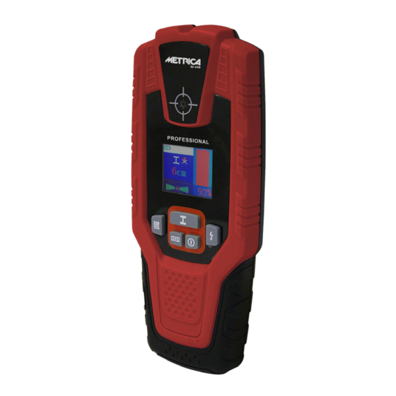
- Page 1 RILEVATORE DIGITALE PROFESSIONALE PROFESSIONAL STUD FINDER DÉTECTEUR PROFESSIONNEL PROFESSIONELLER DETEKTOR Ref. 61530...
-
Page 4: Caratteristiche Del Prodotto
7. Pulsante di rilevamento cavo in tensione ISTRUZIONI 8. Area del sensore 9. Area dell’etichetta del prodotto AVVERTENZA: LO STRUMENTO DI MISURAZIONE POTRÀ 10. Coperchio della batteria ESSERE UTILIZZATO IN MODO OTTIMALE SOLO DOPO AVER LETTO COMPLETAMENTE LE ISTRUZIONI OPERATIVE E SE LE ELEMENTI DEL DISPLAY INFORMAZIONI VERRANNO RIGOROSAMENTE RISPETTATE. - Page 5 PROFONDITÀ ACCURATEZZA OGGETTO DA MISURARE DI RILEVAMENTO DI RILEVAMENTO Ø 20 10cm/8cm Ø 16 8cm/7cm Tondino per cemento armato/ tubo di rame Ø 12 7cm/6cm Ø 6 6cm/5cm ±1cm Cavo e cavo in tensione Trave di legno Legno Stecca di legno NB: Per maggior sicurezza diminuire di almeno 1 cm la misura minima di profondità...
- Page 6 Per calibrare lo strumento: il livello di risposta del segnale rilevato decresce gradualmente - Posizionare lo strumento in un ambiente privo di metalli e di fino a tornare a 0. forti interferenze del campo magnetico (ad es.: tenere lo stru- Quando il risultato sul display raggiunge il massimo valore, si- mento in aria) gnifica che l’oggetto metallico si trova sotto il centro del sensore...
- Page 7 di intensità del segnale cambia da rosso a giallo e poi verde, e Il rilevatore può rilevare cavi attivi da 110 volt, 240 volt e 380 il livello di risposta del segnale rilevato decresce gradualmente volt (AC). fino a tornare a 0. Funzione livella elettronica Quando il risultato sul display raggiunge il massimo valore, si- gnifica che l’oggetto metallico si trova sotto il centro del sensore...
-
Page 8: Dati Tecnici
Per calibrare lo strumento Per non influire sulla funzione di misurazione, nell’area del sen- - Rimuovere tutti gli oggetti metallici nelle vicinanze dello stru- sore “8” sul lato anteriore o posteriore dello strumento non de- mento (compresi orologi da polso o parti metalliche) vono essere applicate decalcomanie / adesivi o targhette identi- - Tenere lo strumento in aria ficative, specialmente se in metallo... -
Page 9: Product Features
9. Product label area INSTRUCTIONS 10. Battery slot cover ATTENTION: THE MEASURING INSTRUMENT CAN BE USED DISPLAY ITEMS OPTIMALLY ONLY AFTER HAVING COMPLETELY READ THE a. Battery indicator OPERATING INSTRUCTIONS AND IF THE GUIDELINES ARE b. Sound icon STRICTLY COMPLIED WITH. c. - Page 10 OBJECT TO BE MEASURED DETECTION DEPTH DETECTION AVCCURACY Ø 20 10cm/8cm Ø 16 8cm/7cm Remarks rod for reinforced concrete / copper pipe Ø 12 7cm/6cm Ø 6 6cm/5cm ±1cm Live wire and cable Wooden beam Wood Wooden batten Note: For a higher safety level, reduce the minimum measurement of the detected depth by at least 1 cm. OPERATION ment with a dry cloth.
- Page 11 Calibration method: When the display shows the maximum value it means that the - Place the instrument where no metal neither strong magnetic metal object is located under the centre of the instrument sensor. interferences are present (e.g.: hold the tool up in the air) The cross of the “g”...
-
Page 12: Maintenance And Cleaning
and the response level of the detected signal decreases gradual- Electronic level function (inclinometer) ly till to return to 0. Press the level button (5) to activate the plane level detection When the display shows the maximum value it means that the function (inclinometer). -
Page 13: Instrument Disposal
- Hold the detector up in the air not apply decals / stickers or identification plates, especially if - When the instrument is on, press the “3”, “5” or “7” button made of metallic material. until the buzzer emits a “dididi” and the green light (1) lights Store and carry the measuring instrument only in the supplied up: the calibration has been completed successfully protective case. - Page 14 7. Bouton de détection de câble de tension INSTRUCTIONS 8. Zone du capteur 9. Zone d’étiquette du produit AVERTISSEMENT: L’INSTRUMENT DE MESURE NE PEUT 10. Couvercle du compartiment de la batterie ÊTRE UTILISÉ DE MANIÈRE OPTIMALE QU’APRÈS AVOIR LU COMPLÈTEMENT LE MODE D’EMPLOI ET SI LES INFORMA- ELÉMENTS D’AFFICHAGE TIONS SONT STRICTEMENT RESPECTÉES.
- Page 15 OBJET À MESURER PROFONDEUR DE DÉTECTION PRÉCISION DE DÉTECTION Ø 20 10cm/8cm Ø 16 8cm/7cm Armature / tube concrete / en cuivre Ø 12 7cm/6cm Ø 6 6cm/5cm ±1cm Câble et câble en tension Poutre en bois Bois Latte en bois NB : Pour plus de sécurité, réduire la mesure minimale de profondeur mesurée d’au moins 1 cm.
- Page 16 Pour calibrer l’instrument: signifie que l’objet métallique est situé sous le centre du capteur - Placer l’instrument dans un environnement exempt de métal de l’instrument. La croix du symbole “g” est affichée sur l’écran. avec de fortes interférences de champ magnétique (ex : Le témoin lumineux clignote en rouge et l’instrument émet un si- maintenir l’instrument dans les airs) gnal acoustique constant.
-
Page 17: Entretien Et Nettoyage
La croix du symbole “g” est affichée sur l’écran. La détection du niveau du plan dans la direction X / Y est une Le voyant (1) clignote en rouge et l’instrument émet un signal fonction automatique de l’instrument. acoustique constant. Les résultats du test sont affichés instantanément sur l’écran NOTE IMPORTANTE POUR LA SÉCURITÉ... -
Page 18: Données Techniques
- Gardez l’instrument en l’air capteur “8” à l’avant ou à l’arrière de l’instrument, ne pas ap- - Un instrument de fonctionnement, appuyez sur la touche « pliquer de décalcomanies / autocollants ou plaques d’identifica- 3 », « 5 » ou « 7 », jusqu’à ce que l’avertisseur sonore émet tion, en particulier si elles sont en métal. -
Page 19: Display-Anzeige
8. Sensorfläche INSTRUKTIONEN 9. Etikettenbereich 10. Batteriefachdeckel WARNUNG: DAS MESSGERÄT KANN ERST NACH VOLL- STÄNDIGEM LESEN DER ANLEITUNG UND BEI GENAUER DISPLAY-ANZEIGE BEACHTUNG DER INFORMATIONEN OPTIMAL GENUTZT a. Batterieanzeige WERDEN. b. Sound-Symbol c. Indikator für Eisen (magnetisch) oder Nichteisenmetall (nicht ANWENDUNG DES WERKZEUGS magnetisch) Das Messgerät dient zur Detektion von Metallen (Eisen-... - Page 20 ZU MESSENDES OBJEKT ORTUNGSTIEFE ORTUNGSGENAUIGKEIT Ø 20 10cm/8cm Ø 16 8cm/7cm Rahmen / Rohr in Kupfer Ø 12 7cm/6cm Ø 6 6cm/5cm ±1cm Kabel und Kabel unter Holzbalken Spannung Holzlatte Hinweis: Verringern Sie zur Erhöhung der Sicherheit die gemessene Mindesttiefe um mindestens 1 cm. BEDIENUNGSANWEISUNGEN Sensorbereich “8”...
- Page 21 kontinuierlich piept und das rote Licht (1) konstant blinkt, muss dert sich die Farbe des Signalstärkepegels von Rot zu Gelb zu das Instrument kalibriert werden. Grün, und der Ansprechpegel des detektierten Signals nimmt allmählich ab, bis er auf 0 zurückkehrt. Kalibrieren: Wenn das Ergebnis auf dem Bildschirm den Maximalwert er- - Stellen Sie das Gerät in eine metallfreie Umgebung mit star-...
-
Page 22: Wartung Und Reinigung
dert sich die Farbe des Signalstärkepegels von Rot zu Gelb zu Elektronische Libelle Grün, und der Ansprechpegel des detektierten Signals nimmt Drücken Sie die Level-Taste (5), um die Level-Detection-Funktion allmählich ab, bis er auf 0 zurückkehrt. (Neigungsmesser) zu aktivieren. Wenn das Ergebnis auf dem Bildschirm den Maximalwert er- Das Erkennen der Neigungen in den Richtungen X / Y ist eine reicht, bedeutet dies, dass sich das Metallobjekt unter der Mitte automatische Funktion des Geräts. -
Page 23: Technische Daten
ments (einschließlich Armbanduhren oder Metallteile) Sensorbereich “8” an der Vorder- oder Rückseite des Geräts kei- - Halten Sie das Instrument in der Luft ne Aufkleber oder Kennzeichnungsschilder auf, besonders dann - Drücken Sie bei einem Bedieninstrument die Taste “3”, “5” nicht, wenn diese aus Metall sind. - Page 24 Importato e Distribuito da: Metrica S.p.A - Via Grandi, 18 20097 San Donato Mil.se (MI) - Italy...
Need help?
Do you have a question about the 61530 and is the answer not in the manual?
Questions and answers