
Related Manuals for Quectel L26-DR EVB

Summary of Contents for Quectel L26-DR EVB
- Page 1 L26-DR EVB User Guide GNSS Module Series Rev. L26-DR_EVB_User_Guide_V1.2 Date: 2019-12-25 Status: Released www.quectel.com...
- Page 2 QUECTEL OFFERS THE INFORMATION AS A SERVICE TO ITS CUSTOMERS. THE INFORMATION PROVIDED IS BASED UPON CUSTOMERS’ REQUIREMENTS. QUECTEL MAKES EVERY EFFORT TO ENSURE THE QUALITY OF THE INFORMATION IT MAKES AVAILABLE. QUECTEL DOES NOT MAKE ANY WARRANTY AS TO THE INFORMATION CONTAINED HEREIN, AND DOES NOT ACCEPT ANY LIABILITY FOR ANY INJURY, LOSS OR DAMAGE OF ANY KIND INCURRED BY USE OF OR RELIANCE UPON THE INFORMATION.
-
Page 3: About The Document
GNSS Module Series L26-DR EVB User Guide About the document History Revision Date Author Description 2019-07-04 Brooke WANG Initial 1. Updated Figure 2, 9 and 15; 2. Updated the description in Chapter 5.2; 2019-11-09 Brooke WANG 3. Updated the calibration procedure in Chapter 7;... -
Page 4: Table Of Contents
Introduction ............................6 1.1. Safety Information ........................6 General Overview ..........................7 2.1. Top and Side Views of L26-DR EVB ................... 7 2.2. L26-DR EVB and Accessories ....................8 2.3. EVB and Accessories Assembly ....................9 Interface Applications ........................10 3.1. - Page 5 GNSS Module Series L26-DR EVB User Guide Table Index TABLE 1: INTERFACES OF L26-DR EVB ......................7 TABLE 2: LIST OF ACCESSORIES ........................8 TABLE 3: SWITCHES AND BUTTONS ......................12 TABLE 4: OPERATION STATUS INDICATION LEDS ..................13 TABLE 5: PIN DESCRIPTION ........................... 14 TABLE 6: RELATED DOCUMENTS ........................
- Page 6 GNSS Module Series L26-DR EVB User Guide Figure Index FIGURE 1: TOP AND SIDE VIEWS OF L26-DR EVB ..................7 FIGURE 2: L26-DR EVB & ACCESSORIES ....................... 8 FIGURE 3: L26-DR EVB AND ACCESSORIES ASSEMBLY ................9 FIGURE 4: MICRO-USB INTERFACE ......................10 FIGURE 5: SD CARD INTERFACE ........................
-
Page 7: Introduction
Quectel L26-DR module. Manufacturers of the terminal should notify users and operating personnel of the following safety information by incorporating these guidelines into all manuals supplied with the product. If not so, Quectel assumes no liability for any failure to comply with these precautions. -
Page 8: General Overview
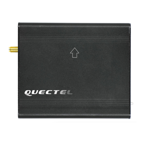
L26-DR EVB User Guide General Overview 2.1. Top and Side Views of L26-DR EVB The following figure illustrates the top and side views of L26-DR EVB. Figure 1: Top and Side Views of L26-DR EVB Table 1: Interfaces of L26-DR EVB... -
Page 9: L26-Dr Evb And Accessories
POWER Power Switch 2.2. L26-DR EVB and Accessories GNSS Antenna USB Flash Drive OBD Cable USB Cable Figure 2: L26-DR EVB & Accessories Table 2: List of Accessories Items Description Quantity The evaluation board of L26-DR USB Cable USB Cable... -
Page 10: Evb And Accessories Assembly
EVB accessories, etc. NOTE L26-DR (UDR) EVB Kit does not contain the OBD Cable. 2.3. EVB and Accessories Assembly The following figure shows the assembly of L26-DR EVB and its accessories. Figure 3: L26-DR EVB and Accessories Assembly L26-DR_EVB_User_Guide 9 / 28... -
Page 11: Interface Applications
GNSS Module Series L26-DR EVB User Guide Interface Applications 3.1. Micro-USB Interface Main power is supplied via the Micro-USB interface. Data can be transmitted via both Micro-USB and SD card interfaces, which is switched between the two interfaces with the USB/SD switch. -
Page 12: Sd Card Interface
GNSS Module Series L26-DR EVB User Guide 3.2. SD Card Interface The SD interface supports to save the output data of L26-DR module in SD card. The storage capacity of supported SD card should be no more than 32GB. Figure 5: SD Card Interface 3.3. -
Page 13: Switches And Buttons
BOOT Please refer to Chapter 4.2.2 for details. POWER Power switch USB/SD switch L26-DR EVB supports data output via both Micro-USB USB/SD and SD card interfaces, which is switched by the USB/SD switch. L26-DR_EVB_User_Guide 12 / 28... -
Page 14: Operation Status Indication Leds
GNSS Module Series L26-DR EVB User Guide 3.5. Operation Status Indication LEDs Figure 8: Operation Status Indication LEDs Table 4: Operation Status Indication LEDs Name Description 1PPS Flash: 1PPS signal indicator. The frequency is 1Hz (configurable). Flash: SD card function is supported. -
Page 15: Obd Interface
GNSS Module Series L26-DR EVB User Guide 3.6. OBD Interface The following figure illustrates the OBD interface of the EVB. Figure 9: OBD Interface Table 5: Pin Description Pin No. Signal Description Ground CAN_L Low level CAN bus line CAN_H... -
Page 16: Evb Operation Procedures
Device Manager of the PC after the USB driver is installed, as shown below. Figure 10: USB Ports Step 3: Install and then use the QCOM tool provided by Quectel to realize the communication between L26-DR module and the PC. -
Page 17: Download Firmware
GNSS Module Series L26-DR EVB User Guide 4.2. Download Firmware There are two methods to download the firmware: firmware upgrade and boot download. 4.2.1. Firmware Upgrade Firmware Upgrade should be operated as the following steps: Step 1: Connect the EVB to a PC through the USB cable. - Page 18 GNSS Module Series L26-DR EVB User Guide Step 3: Release BOOT button to make BOOT pin of L26-DR return to normal floating. Step 4: Run the tool TeseoIII XLoader and configure the tool as shown below. Figure 13: TeseoIII XLoader Tool Configurations Step 5: Click button to download the firmware.
-
Page 19: Usage Of Teseo-Suite Pro
GNSS Module Series L26-DR EVB User Guide Usage of Teseo-Suite Pro After the EVB accessories are assembled, please turn on the module and start the tool Teseo-Suite Pro. The tool helps users to view the status of GNSS receiver. The following chapters only briefly describes the use of Teseo-Suite Pro. - Page 20 GNSS Module Series L26-DR EVB User Guide UART port can be automatically identified by Teseo-Suite Pro when the it is opened. If not, the steps from “a” to “d” illustrated in the following figure should be performed. Please click the corresponding buttons. After button is clicked, the “Rover Configuration”...
-
Page 21: Explanations Of Views And Windows
GNSS Module Series L26-DR EVB User Guide 5.1.2. Explanations of Views and Windows The following interface will be shown by clicking button. The digit shown above each flag is the CN value. Below are displayed information such as the PRN, the frequency band used by the satellite (“BAND”), the azimuth (“AZI”) and the elevation of the satellite (“ELE”). -
Page 22: Send Pstm Commands
GNSS Module Series L26-DR EVB User Guide Through clicking button, "View Positioning" form that shows information about GPS positioning of devices will be opened. Figure 18: Module Positioning Form 5.2. Send PSTM Commands PSTM Commands can be sent by Teseo-Suite Pro. Through clicking button, the command input box will be popped up, which is shown in the figure below. -
Page 23: Calibration Procedure
GNSS Module Series L26-DR EVB User Guide Calibration Procedure In order to utilize Dead Reckoning (DR) capabilities of L26-DR, a valid module calibration is essential. Please mount the module tightly on the vehicle during use. No movement or shaking should occur to ensure the performance of the module. -
Page 24: Main Calibration Procedure
GNSS Module Series L26-DR EVB User Guide direction). Step 4: Drive the vehicle for 1 minute. Step 5: Stop the vehicle and keep it unmoved for at least 5 seconds. The software will save the calculated installation angle to the flash memory. -
Page 25: Calibration Result Monitoring
GNSS Module Series L26-DR EVB User Guide 6.1.3. Calibration Result Monitoring The calibration result can be monitored through Teseo-Suite Pro tool. After the tool is started, please click “DR” in the menu. The “Dead Reckoning” window will be popped up, as shown by the figure below. -
Page 26: L26-Dr (Udr) Evb
GNSS Module Series L26-DR EVB User Guide 6.2. L26-DR (UDR) EVB The installation of L26-DR (UDR) EVB is relatively more demanding, one of the X, Y and Z axis, shown in the following figure, should be perpendicular to the horizontal plane, and the deviation should be less than 20°. -
Page 27: Calibration Result Monitoring
GNSS Module Series L26-DR EVB User Guide 6.2.2. Calibration Result Monitoring The calibration result will be reported in an NMEA ($PQSOL) message. For more details about this message, please refer to document [2]. A method to check the UDR state message is shown by the following figure. -
Page 28: Appendix A Reference
GNSS Module Series L26-DR EVB User Guide Appendix A Reference Table 6: Related Documents Document name Remark Quectel_L26-DR_Hardware_Design L26-DR Hardware Design Quectel_L26-DR_GNSS_Protocol_Specification L26-DR GNSS Protocol Specification Quectel_L26-DR_Reference Design L26-DR Reference Design Quectel_QCOM_User_Guide QCOM User Guide Table 7: Terms and Abbreviations... - Page 29 GNSS Module Series L26-DR EVB User Guide Power Input Pulse Per Second Pseudorandom Noise Satellite Vehicle UART Universal Asynchronous Receiver & Transmitter Coordinated Universal Time L26-DR_EVB_User_Guide 28 / 28...
Need help?
Do you have a question about the L26-DR EVB and is the answer not in the manual?
Questions and answers