Table of Contents
Advertisement
Quick Links
Advertisement
Table of Contents

Related Manuals for Steiss Ashton

Summary of Contents for Steiss Ashton
- Page 1 Ashton Ashton Low General User / Safety Guide...
-
Page 2: Table Of Contents
Contents Section Page General Information General information 1.1. Explanation of the Symbols Used 1.2. Definition of the Groups of Persons Involved Intended Purpose 2.1. Uses for the Purpose Intended (Application Environment) 2.2. Non-compliant Use General Regulations for Users 3.1. Qualification of Users Safety Instructions 4.1. General Safety Instructions 4.2. Safety Information for the Operator 4.3. Safety Information for the User 4.4. Cleaning and Disinfection 4.5. Servicing and Maintenance 4.6. Accessories 4.7. - Page 3 Troubleshooting Care, Cleaning & Disinfection Troubleshooting Servicing 10. Servicing 10.1. Principles Service Record – List of Technical Safety Checks 10.2. according to EN 62353 10.3. Checking the Initial Fault Safety by means of the Integrated Control Box in the Handset 10.4. Measurement of Overall Electrical System 11. Guarantee 12. Service Life & Disposal Technical Specification 13. Technical Specification 13.1. Technical Data (Mechanical) 13.2. Technical Data (Electronic) 13.3. Technical Data (Environmental) 13.4. Classification 13.5. Weights of the Individual Components 13.6. Type Plate EMC Statement Information about electromagnetic emissions...
- Page 4 Cautions & Warnings READ THIS INSTRUCTION MANUAL AND OBSERVE SAFETY INSTRUCTIONS CAUTION WARNING Please read and observe this instruction The side rail guards are manual before each use. In the event the designed to prevent a person care bed changes owners, please supply this falling out of bed; under no instruction manual to the new owner. circumstances should they be climbed or leaned upon.
-
Page 5: General Information
General Information 1. GENERAL INFORMATION Steiss care beds bear the CE mark and meet all safety and functionality requirements. These care beds were tested according to the international BEFORE USING THIS standards which contain the safety requirements BED FOR THE FIRST for medical products. These safety requirements TIME can only be met however if the user satisfies himself of the proper state of the care bed (including accessories) before using the bed. -
Page 6: Definition Of The Groups Of Persons Involved
General Information This care bed may only be used indoors. This product must be disposed of in a separate refuse collection in the European Union. Do not dispose of as normal domestic waste. Symbol for direct current. Symbol for alternating current. Maximum permissible load. -
Page 7: Intended Purpose
General Information 2. INTENDED PURPOSE 2.1. USES FOR THE PURPOSE INTENDED (APPLICATION ENVIRONMENT) This care bed is intended for accommodating patients or occupants (with body mass ≥150cm to max. 185kg for Ashton and Ashton Low) in residential homes, nursing homes and in care in the home (application environments 3 and 4) and may only be used under the conditions for use described in this Instruction Manual. Any other use shall be regarded as non-compliant with the regulations and is excluded from any liability. ATTENTION: The care bed is not designed for use in hospitals. The care bed is not suitable for medical electrical applications which involve intra- vascular or inter-cardiac processes with the patient. The care bed is not designed for the transport of patients. Under certain conditions the care bed can be used for other medical purposes with medical appliances such as antidecubitus mattresses, aerators, alimentation systems etc. In this case all bed functions must be locked out with the nurse key on the... -
Page 8: General Regulations For Users
General Information 3. GENERAL REGULATIONS FOR USERS The care bed must only be used for the purpose intended. When setting up, operating and using the care bed, respect the regulations in your country and the general recognised rules of technology and the occupational health and safety and accident prevention regulations. If the care bed is in a faulty state, in which the patient/ occupant, care personnel or third persons could be endangered, do not operate. - Page 9 General Information Unplug the mains plug from the socket before moving the care bed and take care to avoid dragging the mains plug across the floor when moving the bed. The mains plug must always remain accessible to enable immediate cut-off by unplugging the mains plug from the wall socket in case of emergency. The mains cable must be free and not caught in anything, as it gets carried along when the bed height is adjusted. Otherwise, the mains cable may be torn out and damaged. In addition, the mains plug may be pulled out of its socket and electric leads exposed as a result. If the mains cable or the mains plug are damaged, the relevant part must be replaced. This work should only be carried out by the manufacturer or authorised professionals.
-
Page 10: Safety Information For The Operator
General Information 4.2. SAFETY INFORMATION FOR THE OPERATOR Only persons who have been properly instructed may operate this care bed. This also applies for persons who only operate the care bed on a temporary basis. With the help of this According to the Medical Products Act (German Instruction Manual, instruct abbreviation: MPG, Medizinproduktgesetz), care each user in the safe beds are Class I active medical products. -
Page 11: Cleaning And Disinfection
General Information 4.4. CLEANING & DISINFECTION Before cleaning and disinfection the mains plug must be unplugged and hung up safely. Plugs for the handset and the motors which are plugged into the control box must remain in their sockets. This is necessary to prevent water from getting into the control system. -
Page 12: Accessories
General Information 4.6. ACCESSORIES The optional accessories available include a patient lifting pole of which the safe working load of 80 kg must not be exceeded. The lifting pole may only be used within its admissible adjusting range which is defi ned by the sleeve on the bed. Otherwise the bed may tip up and result in serious injury. 4.7. ELECTROMAGNETIC COMPATIBILITY Regarding their emitted interference and interference resistance the electric motor units comply with the requirements of EN 60601-1-2:2007 (see section 14.7). But it is possible that electrical devices interfere with each other. In this case switch off the care bed for a short time or remove the interference source. We refer to the paper of the BfArm reference n° 9/0508 (Bundesinstitutfür Arzneimittel und Medizinprodukte). 4.8. TRANSPORT & STORAGE The care bed can be easily transported on the transport rack. It can be manoeuvred in... -
Page 13: Installation
Installation 5. PRE-INSTALLATION CHECK Parts list: • Actuators • Control box • Standard and Trendelenburg handset • Side rail fi ngers • End caps • Platform extension • Standard and extended rails • Back up battery and additional accessories After unpacking check the following parts are present: Backrest section with mounted actuator & control box On delivery and before Leg-rest section with mounted installation check that the knee-break actuator packaging is undamaged. 2x height adjustable bed ends Report any visible damage with mounted actuators & castors to Global Consortium Products Ltd immediately. -
Page 14: Installation And Commissioning
Installation 6. INSTALLATION & COMMISSIONING Global Consortium Products Ltd recommends that a risk assessment is completed by the Operator before this bed is assembled. 6.1 REMOVAL FROM THE TRANSPORT DEVICE Lift the cover from the bed unit and transporting device. Please do not dispose of the cover. It can be used again as a dust cover in the event that the care bed is later stored in the transport rack. Bed as delivered Care bed on the transport device Do not remove the cardboard protection from the top of the headboard /footboard sections at this time as it will protect the bed during assembly. - Page 15 Installation Remove the cable tie from the mains adapter and handset. CAUTION Do not damage Handset Mains cable the cable. Remove the height-adjustable head and foot end panels from the transporting device. To do this, release the spring-loaded catches that are later used to fix the height-adjustable head and foot end panels to the mattress base. Pull out catch and turn through 90°.
-
Page 16: Assembly Of The Care Bed
Installation 6.2 ASSEMBLY OF THE CARE BED Connecting the two halves of the mattress base. Lay one platform section face down on the fl oor adjacent to the other half. Then slide the connecting bars together. Secure using the star knobs. Lay the mattress base on the fl oor and attach the fi rst of the bed ends to the mattress base. To do this, apply the brakes on the bed castors by pressing the brake pedal and then release the spring-loaded catches (see 6.2) at the height-adjustable head and foot end panels so the mattress base can be slotted onto the mounting lugs. Lock the foot peddle Connect mattress base Ensure the power cable runs... - Page 17 Installation When securing the spring-loaded catches, ensure the bolt locks into place in the hole provided for it. The bolt of the spring- loaded catch must be securely latched into the hole. Now slot the mattress base into place on the second height-adjustable bed-end panel at the other end of the bed. Fix both the spring-loaded catches securely in place. Now slide the (four) side guards onto the location bolts of the side guard guides, resting the other ends of the side guards on the mattress base at the other end of the bed.
- Page 18 Installation Push the end panel back towards the mattress base and place the base onto the mounting lug. Fix both the spring-loaded catches securely in place. With the side guards slotted into place, the end panel can be pushed back up to the mattress base and secured with the mounting lug. Repeat this procedure on the other side of the bed with the remaining two side guards and fi x the two spring-loaded catches securely to the mattress base.
- Page 19 Installation Connect the height adjustment motors and the thigh rest adjustment motor to the mains power supply. The power supply cables for the height adjustment motors are wound around its housing. Unwind the cable of the electric motor The foot actuator cable MUST go through the yellow cable tie.
-
Page 20: Connecting The Care Bed To The Mains Supply
Installation 6.3. CONNECTING THE CARE BED TO THE MAINS SOCKET Lay the coiled cable over the crossbeam from the head or foot end as shown in the picture. This reduces the risk of the mains cable being crushed when the bed is moved. Always avoid rolling the bed over the mains cable. Insert the mains plug into the socket. The mains plug must always remain accessible to enable immediate removal from the wall socket in case of emergency. The electrical adjustment motors are now ready for use. -
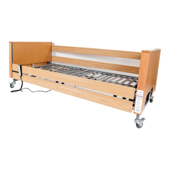
Page 21: Bed Overview
Electrically adjustable thigh rest Mechanically adjustable leg rest Mechanical catch fi tting for adjusting thigh rest Electric height adjustment motor at foot end Electric height adjustment motor at head end Coiled cable with SMPS (transformer) and main cable with power plug Folding mattress guide Wooden side rail (with end caps) (not supplied with the Ashton Low) Side guard channel Castor with mechanical brake Control unit Side Rail Release Catch... -
Page 22: Operation
Operation 7.2. HANDSET WITH LOCKING FUNCTION The motorised bed functions can be operated via the handset. All functions can be locked with the nurses’ key. Backrest adjustment up/down Nurses’ key Thigh rest adjustment Handset hook up/down Handset Backrest and thigh rest locking device up/down adjustment Mattress base height adjustment To operate the mechanical foot rest, first raise the leg section to maximum height then lower again. The mechanism will click. After the third click raise the leg section again, it will now raise the bottom section elevating the whole leg. To avoid damage, the handset should always be hung up by the handset hook (e.g. on mattress base) when not in use. Press only one button at a time, as the system could overload and become damaged. 7.3. -
Page 23: Operation Of The Castors
Operation 7.4. OPERATION OF CASTORS All castors on the bed can be braked and must always be in the braked position during normal operation. Foot pedal to Foot pedal to apply brake. release brake. The brakes must only be released when the beds needs to be moved. Please also refer to the Safety Information. 7.5. ELECTRIC EMERGENCY LOWERING VIA THE INTEGRATED 9V BATTERY 7.5.1. -
Page 24: Maintenance
Maintenance 7.5.2. BATTERY CHANGE To replace, check or remove before lengthy storage of the 9V battery, open the battery compartment on the power supply unit attached to the backrest motor. Proceed as follows: UNPLUG MAINS PLUG Unplug from the low voltage control Pull out the battery carrier (the unit at the plug of the connection black plastic ring protruding from cable from the SMPS transformer box the control box) and remove the 9V battery. -
Page 25: Troubleshooting
Troubleshooting 8. CARE, CLEANING & DISINFECTION Clean and disinfect the bed before placing into service and before each re-use. To clean the care bed, wipe the bed by hand with a damp cloth. Use suitable cleaning and conditioning agents for wooden and synthetic furniture. Household cleaners without ammonium or scouring agents are allowed, but should be dermatologically tested. Solvents and scouring agents are not permitted as they damage the various surfaces of the care bed. To disinfect: In the homepage of the Robert Koch Institute < http://www.rki.de > you will find a list dated of 31.05.2007 of approved and generally accepted disinfection agents and treatments and their use. -
Page 26: Servicing
Servicing 10. SERVICING 10. 1. PRINCIPLES Operators of care beds are obliged according to MPBetreibV (Operators of Medical Products Ordinance) §4 to guarantee the safe condition of the medical product over their entire service life. The test according to the regulation EN 62353 contains the following minimum requirements: • Visual check • Measurement of leakage resistance • Measurement of leakage current • Functional test • Overall evaluation The service life of the care bed depends essentially upon the handling and servicing. To guarantee safe operation, a visual and functional test including an electrical test must be carried out at least once a year. For this purpose, proceed according to the technical safety checklist as per regulation EN 62353 in section 11.2. If you have any doubts about the safety or functionality of the bed or even a part of the bed as a result of the work performed below, the bed should under no circumstances be put into service again. - Page 27 Service Record 10.2. LIST OF TECHNICAL SAFETY CHECKS ACCORDING TO EN 62353 Care bed: ASHTON BED Person in charge ............ Serial No........Location ..............INSTRUCTION FOR TESTING COMMENT Is the general condition OK? Are the type plates for the bed and the motors legible? Is the Instruction Manual available to staff? Is the use one for which it was intended and is it safe? Is there surface damage or corrosion? Mechanical components and welded joints without faults? Are all mechanical connecting elements...
- Page 28 Service Record INSTRUCTION FOR TESTING COMMENT 17 Are all plug-in connections securely attached? (Washers without damage?) 18 Are cables laid correctly and safely? (No damage) 19 Motor housing and SMPS housing, mains plug housing without damage? 20 Are the thrust pipes of the height adjustment motors undamaged? 21 Functional test of the handset: can the buttons be operated properly? 22 Functional test of handset locking device: On/Off working correctly? 23 Testing of initial fault safety by means of integrated blocking box in handset 24 9V block battery OK / expiry date sufficient until next test? 25 Is the safe working load adhered to? Overall evaluation of the bed: Bed OK? Comments ........................
-
Page 29: Checking The Initial Fault Safety By Means Of The Integrated Control Box In The Handset
Servicing 10.3. CHECKING THE INITIAL FAULT SAFETY BY MEANS OF THE INTEGRATED CONTROL BOX IN THE HANDSET To check the safety equipment, proceed as follows: The switching positions I and II are testing settings used only to check the safety during the annual inspection, or after repair work, or each time bed is put into service again. -
Page 30: Guarantee
11. GUARANTEE As stated in our Standard Terms and Conditions, we provide a manufacturer’s warranty of 5 years from the date of purchase. To take advantage of the 5 year warranty, the bed must be serviced (without exception) every 12 months by a Global Consortium Products Ltd approved technician using only Steiss original spare parts. A service record must be completed (an example can be found on pages 29-30). 12. SERVICE LIFE & DISPOSAL The service life of our care beds in domestic use is assumed to be approximately 5 years. This naturally depends upon the manner of use. The carebed is suitable for reuse if all measures of section 6.3 and 10 are taken. Frequent transportation, setting up... -
Page 31: Technical Specification
Technical Specification 13. TECHNICAL SPECIFICATION 13. 1. TECHNICAL DATA (MECHANICAL) Ashton & Ashton Low Safe working load (max. admissible load) 220 kg Individual loads of the safe working load Max. weight of patient 185kg Mattress 20kg Accessories 15kg Total 220kg Safe load, patient’s lifting pole 80 kg Max. weight of patient 185kg Max. mattress height 205mm Length 2150mm (2000mm long mattress) Width 1020mm (900mm wide mattress) Upper level of head section/foot section Ashton: 86.5cm – 129cm Ashton Low: 79cm – 121.5cm Height adjustment of mattress base continually adjustable electrically from: Ashton: 385 - 810mm Ashton Low: 222 - 645mm Backrest adjustment continually adjustable electrically up to approx. 70°... -
Page 32: Technical Data (Electronic)
13.2. TECHNICAL DATA (ELECTRONIC) Power supply unit (LIMOSS) control unit MC220 + SMPS MC125 Voltage rating 230/240V Frequency rating 50/60 Hz Type of current Nominal consumption during operation 70 Watt Nominal consumption in idle state 0.5 Watt Nominal operating time/ Nominal idle time 2 Min. / 18 Min (max. 5 switching cycles/ min.) Primary safety fuse 2.0 A Battery for emergency lowering 9V block battery (alkaline manganese type 6LR61) Mattress base motor unit (back) MD100 (Fa. LIMOSS) Mattress base motor unit (knee) MD125 (Fa. LIMOSS) Height adjustment motor unit 2x MD121 (Fa. LIMOSS) Motor unit protection class IPX4 13.3. TECHNICAL DATA (ENVIRONMENT) Temperature range during operation +10°C to + 40°C Temperature range for storage/transport -10°C to + 60°C Humidity of the air 30% to 75% RH. Air pressure between 700 and 1060 hPa 13.4. -
Page 33: Weights Of The Individual Components
13.5. WEIGHTS OF INDIVIDUAL COMPONENTS Mattress base / Head side 24.0kg Mattress base / Foot side 20.5kg Head end / Foot end Ashton: 17.0 Kg/Pc / Ashton Low: 17.5 kg/Pc Wooden side guards 10.5kg Patient’s lifting pole 4.2kg Transporting device 3.4kg... -
Page 34: Type Plate
Products Ltd Charwood House Wilberforce Way Oakhurst Business Park Ashton Southwater West Sussex RH13 9RT SERIAL NO: 10-40001 00001S 230V/240V ˜ 50/60Hz - 250W IPX4 FUNCTION 2 MIN / PAUSE 18 MIN 185KG 220KG 1 2 3 4 5 6 7 8 9 10 11 12 2018 / 2019 Global Consortium Products Ltd Charwood House Wilberforce Way Oakhurst Business Park Ashton Low Southwater West Sussex RH13 9RT SERIAL NO: 10-40001 00001S 230V/240V ˜ 50/60Hz - 250W IPX4 FUNCTION 2 MIN / PAUSE 18 MIN 185KG 220KG... -
Page 35: Emc Statement
EMC Statement 14. INFORMATION ABOUT ELECTROMAGNETIC EMISSIONS Guidance and manufacturer’s declaration – electromagnetic emissions The care bed is intended for use in the electromagnetic environment specified below. The customer or user of the care bed should ensure that it is used in such an environment. EMISSION COMPLIANCE ELECTROMAGNETIC ENVIRONMENT GUIDELINES RF emissions according Group 1 The care bed uses RF energy only for to CISPR11 its internal functioning. Therefore, its RF emissions are very low and it is unlikely that nearby electronic devices will be disturbed RF emissions according Class B... - Page 36 EMC Statement Guidance and Manufacturer’s Declarations – Electromagnetic Interference Immunity The care bed is intended for use in the electromagnetic environment specified below. The customer or user of the care bed should ensure that it is used in such an environment. INTERFERENCE IEC 60601 COMPLIANCE ELECTROMAGNETIC LEVEL ENVIRONMENT GUIDELINES Electrostatic ± 6 kV contact ± 6 kV contact Floors should be wood, discharge (ESD) discharge discharge concrete or ceramic tile floors according to IEC ± 8 kV air ± 8 kV air...
- Page 37 EMC Statement Guidance and Manufacturer’s Declarations – Non-life-support devices Electromagnetic Interference Immunity. The care bed is intended for use in the electromagnetic environment specified below. The customer or user of the care bed should ensure that it is used in such an environment. INTERFERENCE IEC 60601 COMPLIANCE ELECTROMAGNETIC LEVEL ENVIRONMENT GUIDELINES Conducted RF 3 V eff 3 V eff Portable and mobile radios, interferences 150 kHz including cables, should not 3 V/m according to IEC - 80 MHz...
- Page 38 EMC Statement a. Field strengths from fixed transmitters, such as base stations of mobile telephones and land mobile radios, amateur radio, AM and FM radio and TV broadcast can not be predicted theoretically with accuracy. To assess the electromagnetic environment due to fixed RF transmitters, an electromagnetic site survey is recommended. If the field strength at the location of the care bed exceeds the specified compliance level above, then the care bed should be monitored with respect to its normal operation. If abnormal performance is observed, it may be necessary to take additional measures, such as reorienting or relocating the care bed. b. Over the frequency range 150 kHz to 80 MHz, field strengths should be less than 3 V/m. Recommended working clearances between portable and mobile RF communications equipment and the care bed. The care bed is intended for use in an electromagnetic environment in which radiated RF disturbances are controlled. The customer or user of the care bed can help to prevent electromagnetic interference by maintaining a minimum distance between portable and mobile RF.
- Page 39 EMC Statement OUTPUT POWER OF WORKING CLEARANCE ACCORDING TO TRANSMITTER – W TRANSMISSION FREQUENCY – M 150 kHz to 80 MHz 80 MHz to 800 MHz 800 MHz to 2.5 GHz at 3 V/m at 3 V/m at 3 V/m d = [ ]√P d = [ ]√P d = [ ]√P 0.01 0.12 0.12 0.23 0.38 0.38 0.73 For transmitters not rated in the list above, the working clearance can be determined using the equation, which belongs to the transmitter, where P is the nominal output of the transmitter in watts (W) according to specifications of the transmitter manufacturer.
-
Page 40: Declaration Of Conformity
Annex VII EU Directive 93/42/EEC We, as company: Global Consortium Products Ltd Charwood House Wiberforce Way Oakhurst Business Park Southwater RH13 9RT Confirm on our own behalf that the medical product handicapped accessible bed/home-care bed models: • ASHTON • ASHTON LOW Complies with all applicable requirements in Appendix I of the EU directive 93/42/EEC. The following compliance evaluation process was applied: Annex VII In the event of modification of this product without consultation with the manufacturer, this declaration of conformity will lose its validity. Dated: 23/07/2018 Russell Andrews Head of Procurement... -
Page 41: Date Of Purchase
Date of Purchase Date of purchase ......................Distributor stamp: You can fix your receipt here:... - Page 42 Notes:...
- Page 44 ™ Global Consortium Products Limited This product is made from the best All parts and data continually undergo Charwood House materials using the latest manufacturing further development and may therefore Wilberforce Way techniques, and gives the guarantee deviate from the details given. Oakhurst Business Park of quality. Southwater West Sussex RH13 9RT...
Need help?
Do you have a question about the Ashton and is the answer not in the manual?
Questions and answers