Table of Contents
Advertisement
Quick Links
Advertisement
Table of Contents

Subscribe to Our Youtube Channel
Related Manuals for SMAR HI302

Summary of Contents for SMAR HI302
- Page 1 AGO / 02 FOUNDATION 3 2 F M E...
- Page 2 CHINA FRANCE Smar Equipamentos Ind. Ltda. Smar Argentina Smar China Corp. Smar France S. A. R. L. Rua Dr. Antonio Furlan Jr., 1028 Soldado de La Independencia, 1259 3 Baishiqiao Road, Suite 30233 42, rue du Pavé des Gardes Sertãozinho - SP 14170-480 (1429) Capital Federal –...
- Page 3 Introduction Introduction The HI302 is a hardware component integral to System 302 which main function is to interface HART devices to Foundation Fieldbus Systems, allowing the user to perform maintenance, calibration, sensor status monitoring, device status, among others information. See below some HI302 features: •...
- Page 4 HI302 - User’s Manual...
- Page 5 Configuring the HIRT Block ....................3.5 Configuring the HVT Block.....................3.7 HI302-I – Configuring the MAI Block..................3.7 HI302-O – Configuring the MAO Block ..................3.8 Starting the HI302 Operation ....................3.8 CHAPTER 4 – ADVANCED CONFIGURATION ................4.1 HART Command Definition with HCD and HWPC Blocks ............4.1 Configuration for Specific HART Commands ................4.1...
- Page 6 Processing Core........................6.3 HI302 Module Resetting......................6.4 H1 Fieldbus Communication ....................6.5 HART Communication ......................6.5 4-20 mA to Foundation Fieldbus Analog Conversion (HI302-I) ..........6.5 Foundation Fieldbus to 4-20 mA Analog Conversion (HI302-O) ...........6.6 CHAPTER 7 – AN EXAMPLE OF HI302 USAGE................7.1 Installation ..........................7.1 Step by Step Configuration ....................7.1...
-
Page 7: General Vision
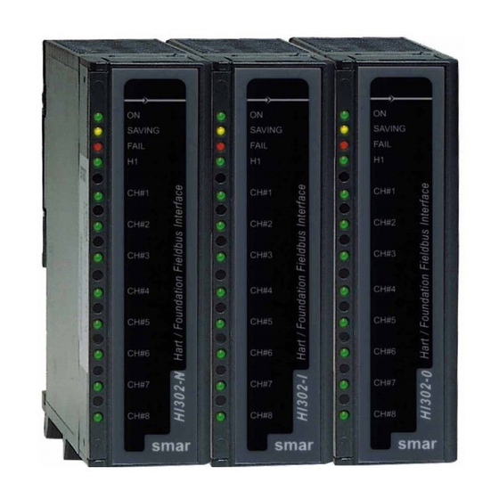
There are three models for the HI302, according to the analog conversion needs: • HI302 – N: only HART communication; • HI302 – I : HART communication and conversion of eight 4-2- mA analog inputs to FF; • HI302 – O: HART communication and FF conversion to eight 4-20 mA analog outputs;... -
Page 8: Function Blocks
There should be one HIRT block for each HART device installed, up to 32 blocks. In normal operation, the HIRT block parameters show the HART device variables, since there are mechanisms to keep the HI302 database updated. See the Appendix A or the Function Blocks handbook for details. - Page 9 See table with detailed definitions on the Appendix A blocks. In order to support the analog circuits on HI302-I and HI302-O modules, use the MAI or MAO blocks, respectively, to convert the analog 4-20 mA standard to FF or FF to 4-20 mA.
- Page 10 General Vision...
- Page 11 HI302 installation set: BASIC SET The HI302 requires just one 5V @ 500 mA power supply. We recommend the Smar PS- AC or DF50 power supply modules. Besides providing a high quality feeding, they also provide a “Power Fail”...
-
Page 12: Electrical Connection
IMPORTANT Since the HI302 H1 channel is a passive channel, it is not necessary to use the bus power supply. For instance, if the DF51 channel is connected to the HI302 channel, they will communicate normally. - Page 13 HI302 - User’s Manual The following picture shows an example of an HI302-N connection focused on the HART communication. In this case, connect more devices, up to 32, in parallel, to perform a multidrop communication. In order to simplify the connection below, connect the HART channel in parallel to the device, instead of connecting it in parallel to the resistor.
- Page 14 20 mA analog signal, since the average value of a FSK modulated signal is zero. Thus, if the HART device is already installed, make sure that the minimum impedance (25Ω) is used and connect the HI302 channel in parallel to the device. Device Physical Types...
- Page 15 HART Installation Topology The HI302 comply with several applications, since the new ones to older installations, where it is necessary to increase the HART device’s life span and preserve the investment with the gradual introduction of the Foundation Fieldbus technology. Below are some examples of connections.
- Page 16 Besides its complexity, this connection allows an improvement in the use of the HI302 channels and, as the current that flows in the loop is tenths of mA, use an active impedance instead of a simple resistor. See the next picture:...
- Page 17 This kind of topology doesn’t have necessarily the 250Ω external resistor connected in series with each device, since there is a 4-20 mA sampling resistor on the HI302 analog board serial to the loop. Be careful with a short-circuit in the loop, because the HI302’s internal resistor may be damaged.
-
Page 18: Maximum Cable Length
See some common types as follow. Portable Configurator As we mentioned before, the HI302 operates as a master in most applications. So, there is no problem in using a portable configurator, such as a HP301. Whatever the installation topology, make sure to install a 25 Ohms impedance serial to the power supply. If no active impedance or resistors are installed, the secondary master device will not communicate. - Page 19 Before you begin the update, the HI302 module must be set in the boot loader mode. To do so, press the Reset button located at the upper right side in the front part of the module.
- Page 20 Installation 2.10...
-
Page 21: Basic Configuration
• 1 HCD block and 1 HWPC block for each specific configuration (that is) not stored in the FLASH memory. The configuration for Smar devices is embedded in the FLASH memory. See the Appendix for more details. The maximum block limit and its quantity in the factory configuration are shown below:... - Page 22 It can operate in two ways: if the parameter is Autonomous, the HI302 communicates with the HART devices by using the previous configuration, i.e., in an independent way. The second way uses bypass parameters to send and receive HART messages. To do so, this parameter should be...
- Page 23 • RETRIES: This parameter adjusts the number of times the HI302 will try to communicate with a device, before detecting that this device doesn’t respond anymore. The standard value is 3 retries.
- Page 24 ♦ VALID_RX_FRAMES: Totalizes the number of valid messages received and processed by the HI302, even if they are not addressed to it, for example, OACK, OBACK, STX etc.
- Page 25 HIRT block for each HART device installed and that the configuration may vary according to the application mode and type. A minimum set of parameters needs a configuration to allow the HI302 to work properly. Most of the parameters have standard values that are suitable for many operation cases.
- Page 26 OS and then, on AUTO. • Automatic: In this case, if the device was not recognized at the first time or does not respond, the HI302 will wait and then it will start a new identification. This is a standard value.
- Page 27 Functioning Theory for more details. HI302-I - Configuring the MAI Block All HI302-I inputs have an input circuit for the 4-20 mA acquisition. So, it is possible to instantiate a block with a multiple analog input or with 8-output parameters that provide the percentage value of the analog input related to the 16 mA range (4 mA = 0% and 20 mA = 100%).
- Page 28 Basic Configuration HI302-O – Configuring the MAO Block The HI302-O has 8 HART channels in parallel to circuits that control the loop current and the actuators connected to them. The input parameter value should always be written in percentage of Span. The following parameters should be configured: •...
-
Page 29: Advanced Configuration
Specific Commands: These commands allow the user total operation flexibility. Thus, it is possible to know their syntax. To do so, the HI302 has blocks that allow the user to make a configuration to use any accessed variable (reading or writing variable) - Page 30 Advanced Configuration Commands See below some examples of HART commands and how to create a reading and writing configuration for the variables. For a more detailed explanation, see the device manual. We will use Universal Commands, although any HART command can be described the same way.
- Page 31 HI302 - User’s Manual Command-Specific Response Codes Code Class Description Success No Command-Specific Errors Undefined Error Device-Specific Command Error Undefined Warning Update Failure 9-15 Undefined Error Access Restricted 17-127 Undefined Command 18 - This command writes the Tag, the Descriptor and the Date into the device.
- Page 32 Advanced Configuration Configuring the HCD block Mapping the HART variable as FF parameters To configure the HCD block, the user should have the HART documentation describing the commands to be used. Using the HART command description, the user should list the HART variables to be accessed, paying attention to their type (1 byte, 3 bytes, float, ASCII, etc).
-
Page 33: Request Parameters
HI302 - User’s Manual After the definition header, there is the command definition composed of fields with four bytes each. Each four byte-field defines a HART variable used in the command sending or received in the answer. In the HCD block, there are definition parameters with 10 and 25 variables. - Page 34 Advanced Configuration Setting the HWPC block Configuration The HWPC block completes the configuration done in the HCD block. For each HCD block with parameters that can be written, it is necessary to have a corresponding HWPC block with the same code in the definition library HCD_CODE. The HWPC block parameters have the following structure: 1.
-
Page 35: Operation
However, to avoid the premature wear off of the memory, use a mirror of its contents in SRAM. While this LED remains lit, avoid the HI302 to be switched off or reset, as this will indicate that static data from the SRAM mirror is being saved on the EEPROM. - Page 36 This LED indicates that an activity is going on in the Fieldbus Communication. At each information package sent by the HI302, the LED will blink. If the LED doesn’t blink, it indicates that the HI302 is not communicating with the net. Switch off the HI302 and restart it a few minutes later.
- Page 37 ID_CMD parameter. If the ID_METHOD parameter is set on Automatic, the HI302 will identify the device. If the ID_METHOD = Manual, set the block at OS and, then change to AUTO. Then, it goes to the IDENTIFICATION status.
- Page 38 IMPORTANT The POLL_CTRL parameter should be set on Enabled to allow for the HI302 to poll the device. In addition to updating the dynamic variables, the polling also updates the parameters that depend on the RESPONSE_CODE parameter, for example, DS-65 and DEVICE_STATUS.
- Page 39 6. In normal operation, the alteration flag, located in the Response Code, is checked at each transaction. If this flag is set, the HI302 starts a reading sequence on the parameter of the HIRT block, that is, the BLK_EXEC_STATE parameter goes to IDENTIFICATION. The HVT block does not update automatically and its ST REV parameter has no useful meaning.
- Page 40 HCD block and will be sent to the device. IMPORTANT Despite the fact that the HI302 has responded and the writing was successful, the value read on the parameter continues to be the old one. The new value is in a temporary variable and the parameter will be updated after the writing confirmation in the HART device.
- Page 41 HVT block that connects the HART variables on the device with the block parameters, whose names are generic ones. The devices can be fully defined using the HIRT+HVT blocks. See below an example of a HVT allocation map for Smar FY301 intelligent positioners: Index Parameter Name...
- Page 42 4. If there is one, the block checks if the TAG belongs to a HIRT block that corresponds to a device installed in one HI302’s channel. If the TAG was not found, the status will be TAG NOT FOUND and the process will be aborted.
- Page 43 Smar HPC301. If some alteration happens on the device, it (the programmer) will report this to the HI302 in its next response, through the specific bit RESPONSE CODE. Then the HI302 will take the following actions: •...
-
Page 44: Bypass Mode
Operation • If the polling is enabled, the HIRT block associated with the HART device will notice this alteration and will go to OLD DATA, sending the command 38. • After sending the command, the HIRT block begins to update the parameters by getting in IDENTIFICATION and UPDATING. - Page 45 TIMEOUT, after a predefined number of repetitions, it was not possible to receive a valid message for the request. The HI302 does not perform any integrity or content checkup on the message received. It transmits what it has received to the communication channel. The applicative must ensure the quality of the messages and the response interpretation.
- Page 46 Operation 5.12...
- Page 47 Chapter 6 Basic Functioning Theory This chapter presents basic concepts on HI302 hardware to help the user to solve field and maintenance problems. The HI302 Block Diagram The picture below shows the block diagram for the HI302:...
- Page 48 This is important when the HI302 is being fed by a shared source, e.g., a rack with other HI302 or DF51 modules. In addition to a 5V source, the HI302 should receive a failure signal from the source (/PFAILR), working at a low level.
-
Page 49: Processing Core
NOT WORK. Note that grounding resistance must be measured every 2 years. Processing Core The core of the HI302 module is based on the 68HC11 (U1) microcontroller running at 10 MHz (Y1): one of the most reliable and well accepted components in the whole world. - Page 50 Hand RESET key and FACTORY INIT In the front side of the HI302 module there are two push button keys. One of them is the Hand RESET button, connected to the U5, that covers the following components: HC11 (U1), FB3050 (U2), EPLD (U10) and UARTs (U7 and U8).
-
Page 51: Hart Communication
1200 to 2200 Hz (fundamentals). Next, a comparator (U27A) changes the signal received and amplified in a square wave, for it to be decodified by the Smar HT2012 HART modem (U35). The transmission is made by switching a 22uF electrolytic capacitor that works integrating the signal modulated by the HT2012. - Page 52 Basic Functioning Theory Foundation Fieldbus to 4-20mA Analog Conversion (HI302-O) In a similar way, a board with analog output circuits is capable of controlling a current used by actuators, for example. These circuits are protected against high voltage by zener diodes, against overheating and against inverted polarity.
-
Page 53: Installation
HI302-I Step by Step Configuration 1. When the HI302 is fed by the rack and is switched on, press the Fct Init button to initialize the factory configuration. The device will reset and then light the yellow LED SAVING and all LEDs on the HART channels. - Page 54 An Example of HI302 Usage 5. Let’s now fill up the basic parameters on the HIRT block so that the HI302 communicates with the HART device. This minimum configuration makes it possible for the HI302 find the device and start the communication. In fact, let’s see: •...
- Page 55 HI302 – User’s Manual 6. After filling up the essential parameters, just Download the configuration. See the screen below: Before trying to monitor any block, don’t forget to update the OPC Server’s data base, by using any of the options below: Step by Step Operation 8.
- Page 56 If not, check if the block is being executed. The MODE_BLK.ACTUAL parameter should be AUTO. 11. After identifying the device and filling up the HIRT block, the HI302 will continually send the HART 33 command, since this is the polling command by default, by which default the polling is enabled.
- Page 57 HI302 – User’s Manual...
- Page 58 An Example of HI302 Usage 12. When on UPDATED, just proceed as if with any common parameter, in order to write it in any parameter that accepts writing, as for example, MESSAGE. Note that the BLK_EXEC_STATE parameter passes by three states: WRITING, OLD DATA and UPDATED.
- Page 59 HI302 – User’s Manual...
- Page 60 An Example of HI302 Usage...
-
Page 61: Troubleshooting
Chapter 8 Troubleshooting Installation Problem Solution • Increase the impedance measured from the HI302 terminals if it is less When 250Ω than 250Ω. Maybe, it is necessary to increase the supply voltage. resistor. • See the “Impedance x Minimum Supply Voltage” graphic in the Chapter 2. - Page 62 Thus, the HI302 module may be connected to any existing installation. 2. Does the HI302 Module work with Third party Devices, that is, those not made by Smar? Yes. HI302 was designed to work with any devices that comply with HFC (HART Communication Foundation) norms.
- Page 63 9. Does the HI302 Module let Portable Programmers to be used, such as the HPC301? Yes. Since the HPC301 is a Secondary Host, it is possible to have it connected to a HI302 channel without any problems, provided this channel is configured as a Primary Host.
- Page 64 Troubleshooting...
- Page 65 Appendix A HCFG - HART Configuration Transducer Block Index Parameter Data Type Valid Range / Options Default Value Units Store / Mode Description BLOCK_STRUCTURE DS-64 ST_REV Unsigned16 None S / RO TAG_DESC OctString(32) Spaces STRATEGY Unsigned16 None ALERT_KEY Unsigned8 1 to 255 None MODE_BLK DS-69...
- Page 66 HI302 – User’s Manual Index Parameter Data Type Valid Range / Options Default Value Units Store / Mode Description 0x00: Idle, This array shows the status of the bypass execution for all the channels BYPASS_STATUS Unsigned8[8] 0x01: Busy, 0x00: Idle, D / RO and must be supervised for response check purposes.
- Page 67 21: 21 - Long Tag This parameter controls the method of device (re) identification. If Automatic, HI302 will (re) try to identify the device always the device is in an unidentified condition after a pre-determined delay. If Manual, the 0x00: Automatic...
- Page 68 HI302 – User’s Manual HART Hart Index Parameter Data Type Valid Range / Options Default Value Units Store/Mode Description Read Write Device's Unique ID (MAN_ID, DEV_TYPE, DEV_ID). (0, 11, 21) UNIQUE_ID OctString(5) {0, 0, 0, 0, 0} D / RO...
- Page 69 Appendix A HART Hart Index Parameter Data Type Valid Range / Options Default Value Units Store/Mode Description Read Write PV_ULRUC Enumerated HC TABLE 2 None PV Upper & Lower Range Value Units Code PV_RANGE.EU_100: HART PV Upper Range Value, PV_RANGE.EU_0: HART PV Lower Range Value, XD_SC PV_RANGE DS-68...
- Page 70 HI302 – User’s Manual HART Hart Index Parameter Data Type Valid Range / Options Default Value Units Store/Mode Description Read Write 9 or 33 S3_UC Enumerated HC TABLE 2 None Slot 3 variable Units Code. S3_VAL.Value: actual Slot 0 variable Value,...
- Page 71 Appendix A HVT – HART Variable Template Index Parameter Data Type Valid Range / Options Default Value Units Store / Mode Description BLOCK_STRUCTURE DS-64 ST_REV Unsigned16 None S / RO TAG_DESC OctString(32) Spaces STRATEGY Unsigned16 None ALERT_KEY Unsigned8 1 to 255 None MODE_BLK DS-69...
- Page 72 HI302 – User’s Manual Index Parameter Data Type Valid Range / Options Default Value Units Store / Mode Description String_03 VisibleString(8) Spaces 8 characters general use string String_04 VisibleString(8) Spaces 8 characters general use string String_05 VisibleString(8) Spaces 8 characters general use string...
- Page 73 BLK_ERR Bitstring(2) None D / RO Template code from Template Library. 0 to 33000 are reserved for smar's 33000 to 65535: allowed library. 0 to 16384 are stored into FLASH, in such way that 0 to 8194 will HCD_CODE Unsigned16...
- Page 74 HI302 – User’s Manual Index Parameter Data Type Valid Range / Options Default Value Units Store / Mode Description Request and Response CMD_16 OctString(44) See HART Command configuration parameters. parameters Request and Response CMD_17 OctString(44) See HART Command configuration parameters.
- Page 75 Appendix A Index Parameter Data Type Valid Range / Options Default Value Units Store / Mode Description parameters Request and Response CMD_44 OctString(104) See HART Command configuration parameters. parameters Request and Response CMD_45 OctString(104) See HART Command configuration parameters. parameters Request and Response CMD_46 OctString(104)
- Page 76 HI302 – User’s Manual HWPC – HART Writeable Parameter to Command Correlation Index Parameter Data Type Valid Range / Options Default Value Units Store / Mode Description BLOCK_STRUCTURE DS-64 ST_REV Unsigned16 None S / RO TAG_DESC OctString(32) Spaces STRATEGY Unsigned16...
- Page 77 HART Command Configuration in FLASH memory HIRT Block When the device is identified by the command selected in the HIRT.ID_CMD, the HI302 module will send sequentially all the reading commands in the configuration selected in the HIRT.HCD_SEL.[1] parameter. Since this set of commands includes some Common Practice commands, the device may not support all the sent commands, causing, then, retransmission and time waste in the communication.
- Page 78 HIRT.HCD_SEL parameter when performing the block configuration. The codes below correspond to the HCD blocks stored in the FLASH memory. The codes from 0 to 33000 are reserved for Smar configuration. The codes above 33000 until 65535 are free to be configured by the users.
- Page 79 Appendix C HVT ALLOCATION MAP FOR FY301 V2.12 Index Parameter Name HART Variable Name HART Command Description 11.1 U8B_ARRAY_1[1] EEPROM_CONTROL EEPROM Control 11.2 U8B_ARRAY_1[2] DISPLAY_CONNECTED Indicates if the Display is connected or not 11.3 U8B_ARRAY_1[3] AIR_TO 128,129 Air to (open or close) 11.4 U8B_ARRAY_1[4] LOCAL_KEYS_MODE_CTL...
- Page 80 HI302 – User’s Manual HVT ALLOCATION MAP FOR FY301 V2.12 Index Parameter Name HART Variable Name HART Command Description 12.20 U8B_ARRAY_2[20] TRAVEL_LIMIT_UNIT Travel_limit unit 13.1 U8B_ARRAY_3[1] TRAVEL_RANGE_UNIT Travel_Range unit 13.2 U8B_ARRAY_3[2] MILEAGE_UNIT 190,237 Mileage unit 13.3 U8B_ARRAY_3[3] PRESSURE_STATUS Pressure Sensor status 13.6...
- Page 81 Appendix C HVT ALLOCATION MAP FOR FY301 V2.12 Index Parameter Name HART Variable Name HART Command Description 16.4 FLOAT_ARRAY_1[4] TRIM_PRESSURE_OUT1_UPPER Trim Pressure Out1 Upper 16.5 FLOAT_ARRAY_1[5] TRIM_PRESSURE_OUT1_LOWER Trim Pressure Out1 Lower 16.6 FLOAT_ARRAY_1[6] TRIM_PRESSURE_OUT2_UPPER Trim Pressure Out2 Upper 16.7 FLOAT_ARRAY_1[7] PRESSURE_LOW_LIMIT 244,245 Lower pressure limit for the input sensor...
- Page 82 HI302 – User’s Manual HVT ALLOCATION MAP FOR FY301 V2.12 Index Parameter Name HART Variable Name HART Command Description 17.17 FLOAT_ARRAY_2[17] SP_RATE_UP_TIME_DIAG_REF SP_Rate Up_time Diagnosis References 17.18 FLOAT_ARRAY_2[18] SP_RATE_DN_TIME_DIAG_REF SP_Rate Dn_Time Diagnosis References 17.19 FLOAT_ARRAY_2[19] PID_KP_DIAG_REF Pid gain value 17.20...
- Page 83 Appendix C HVT ALLOCATION MAP FOR FY301 V2.12 Index Parameter Name HART Variable Name HART Command Description 19.11 FLOAT_ARRAY_4[11] Y2 133,134 Table Coord Y2 19.12 FLOAT_ARRAY_4[12] Y3 133,134 Table Coord Y3 19.13 FLOAT_ARRAY_4[13] Y4 133,134 Table Coord Y4 19.14 FLOAT_ARRAY_4[14] Y5 133,134 Table Coord Y5 19.15...
- Page 84 HI302 – User’s Manual HVT ALLOCATION MAP FOR SMAR LD301 V6.01 Index Parameter Name HART Variable Name HART Command Description 11.1 U8B_ARRAY_1[1] FLANGE_TYPE 128,129 Flange Type 11.2 U8B_ARRAY_1[2] FLANGE_MATERIAL 128,129 Flange Material 11.3 U8B_ARRAY_1[3] O_RING 128,129 O_Ring 11.4 U8B_ARRAY_1[4] METER_INSTALLATION...
- Page 85 Appendix C HVT ALLOCATION MAP FOR SMAR LD301 V6.01 Index Parameter Name HART Variable Name HART Command Description 12.18 U8B_ARRAY_2[18] MEASURED_POINT_UNIT Measured Point Unit 12.19 U8B_ARRAY_2[19] CHAR_AND_DISPLAY_MODE Characterization Trim mode and Display 12.20 U8B_ARRAY_2[20] LOAD_RESTORE_TRIM Load/Restore Trim 13.1 U8B_ARRAY_3[1] FIRST_DISPLAY_CODE...
- Page 86 HI302 – User’s Manual HVT ALLOCATION MAP FOR SMAR LD301 V6.01 Index Parameter Name HART Variable Name HART Command Description 14.12 U8B_ARRAY_4[12] WRITE_SENSOR Write Sensor 16.1 FLOAT_ARRAY_1[1] PV_CURR_LEVEL_DAC_ZERO Set value of the Trim Primary Variable Current Dac Zero 16.2 FLOAT_ARRAY_1[2]...
- Page 87 Appendix C HVT ALLOCATION MAP FOR SMAR LD301 V6.01 Index Parameter Name HART Variable Name HART Command Description 17.16 FLOAT_ARRAY_2[16] 133,134 Table Coord X1 17.17 FLOAT_ARRAY_2[17] 133,134 Table Coord X2 17.18 FLOAT_ARRAY_2[18] 133,134 Table Coord X3 17.19 FLOAT_ARRAY_2[19] 133,134 Table Coord X4 17.20 FLOAT_ARRAY_2[20]...
- Page 88 HI302 – User’s Manual HVT ALLOCATION MAP FOR SMAR LD301 V6.01 Index Parameter Name HART Variable Name HART Command Description 19.10 FLOAT_ARRAY_4[10] ACTUAL_POINT_3 160,162 Actual characterization Trim Curve Point 3 19.11 FLOAT_ARRAY_4[11] ACTUAL_POINT_4 160,162 Actual characterization Trim Curve Point 4 19.12 FLOAT_ARRAY_4[12]...
- Page 89 Appendix C HVT ALLOCATION MAP FOR SMAR TT301 V2.04 Index Parameter Name HART Variable Name HART Command Description 11.1 U8B_ARRAY_1[1] EEPROM_CONTROL Eeprom Control 11.2 U8B_ARRAY_1[2] PV_XMTR 50.51 Transmitter Variable Assigned to the Primary Variable 11.3 U8B_ARRAY_1[3] SV_XMTR 50.51 Transmitter Variable Assigned to the Secondary Variable 11.4...
- Page 90 HI302 – User’s Manual HVT ALLOCATION MAP FOR SMAR TT301 V2.04 Index Parameter Name HART Variable Name HART Command Description 12.17 U8B_ARRAY_2[17] ALARM_2_ACKNOWLEDGE 159,161 Acknowledge alarm 2 12.18 U8B_ARRAY_2[18] FAIL_SAFE_MODE 162,163 Fail_safe mode (low or high) 12.19 U8B_ARRAY_2[19] PV_DISPLAY 164,165 PV for Display indication 12.20...
- Page 91 Appendix C HVT ALLOCATION MAP FOR SMAR TT301 V2.04 Index Parameter Name HART Variable Name HART Command Description 16.9 FLOAT_ARRAY_1[9] PROPORTIONAL_FACTOR(KP) 142,143 Proportional Factor Value 16.10 FLOAT_ARRAY_1[10] INTEGRAL_TIME(TR) 142,144 Integral Time Value 16.11 FLOAT_ARRAY_1[11] DERIVATIVE_TIME(TD) 142,145 Derivative Time Value 16.12...
- Page 92 HI302 – User’s Manual HVT ALLOCATION MAP FOR SMAR TT301 V2.04 Index Parameter Name HART Variable Name HART Command Description 18.2 FLOAT_ARRAY_3[2] SP_CURVE_X7 156,157 Coordinate X of set point curve index 8 18.3 FLOAT_ARRAY_3[3] SP_CURVE_X8 156,157 Coordinate X of set point curve index 8 18.4...
Need help?
Do you have a question about the HI302 and is the answer not in the manual?
Questions and answers