Table of Contents
Advertisement
®
S&C IntelliRupter
Outdoor Distribution (15.5 kV, 27 kV, and 38 kV)
Table of Contents
Section
Qualified Persons . . . . . . . . . . . . . . . . . . . . . . . . . . . . . 2
Read this Instruction Sheet . . . . . . . . . . . . . . . . . . . . . . 2
Retain this Instruction Sheet . . . . . . . . . . . . . . . . . . . . . 2
Special Warranty Provisions . . . . . . . . . . . . . . . . . . . . . 2
Understanding Safety-Alert Messages . . . . . . . . . . . . . 3
Following Safety Instructions . . . . . . . . . . . . . . . . . . . . . 3
Replacement Instructions and Labels . . . . . . . . . . . . . . 3
. . . . . . . . . . . . . . . . . . . . . . . . . . . . . . . . . . . . . 4
. . . . . . . . . . . . . . . . . . . . . . . . . . . . . . . . . . . . . . . . .5
July 31, 2017
© S&C Electric Company 2013-2017, all rights reserved.
®
PulseCloser
Fault Interrupter
Docking Station Instructions
Page
. . . . . . . . . . . . . . . . . .7
Section
Connect with IntelliLink® Setup Software . . . . . . . . . . .12
Reloading Firmware with Download Utility . . . . . . . . . .13
Verification of Correct Operation . . . . . . . . . . . . . . . . .16
Connect with IntelliLink Setup Software . . . . . . . . . . . .17
Reloading Firmware with Download Utility . . . . . . . . . .19
Verification of Correct Operation . . . . . . . . . . . . . . . . .21
. . . . . . . . . . . . . . . . . . . . . . . . . . . . . . . .22
Instruction Sheet 766-557
Page
. . . . . . . 11
. . . . . . . .23
Advertisement
Table of Contents

Related Manuals for S&C IntelliRupter PulseCloser SDA-4650R2

Summary of Contents for S&C IntelliRupter PulseCloser SDA-4650R2
-
Page 1: Table Of Contents
® ® S&C IntelliRupter PulseCloser Fault Interrupter Outdoor Distribution (15.5 kV, 27 kV, and 38 kV) Docking Station Instructions Table of Contents Section Page Section Page Introduction Serial Connection with a Docking Station . . . . . . . 11 Qualified Persons . -
Page 2: Introduction
Introduction Qualified Persons Ç WARNING The equipment covered by this publication must be installed, operated, and maintained by qualified persons who are knowledgeable in the installation, operation, and maintenance of overhead electric power distribution equipment along with the associated hazards . A qualified person is one who is trained and competent in: •... -
Page 3: Safety Information
Safety Information Understanding There are several types of safety-alert messages which may appear throughout this instruction sheet as well as on labels attached to the IntelliRupter fault interrupter . Safety-Alert Messages Familiarize yourself with these types of messages and the importance of the various signal words, as explained below . -
Page 4: Overview
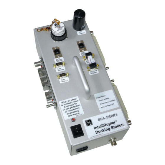
Overview These instructions cover the procedure for operating the IntelliRupter PulseCloser Fault Interrupter Docking Station. This device powers the protection and control module when it is removed from the IntelliRupter fault interrupter, and permits uploading and downloading configuration settings, by using a dedicated base memory module. The docking station can also be used with a communication module when it is removed from the IntelliRupter fault interrupter and installed in the docking station with a protection and control module. -
Page 5: Setup
Setup Step 1 Set up the docking station on a sturdy work surface. If Global Positioning System opera- tion is to be checked, place the docking station near a window, so that satellite signals can be received by the user-furnished GPS antenna. Step 2 Connect the power cord to the docking station. - Page 6 Setup Step 8 To preserve previously programmed settings in the protection and control module: Unscrew the locking ring of the base memory module and unplug the module. NOTICE If the base memory module is not unplugged from the docking station when the docking station is powered up, the protection and control module will upload the most recently applied settings stored in the base memory module .
-
Page 7: Establishing Wi-Fi Connection
Establishing Wi-Fi Connection The Wi-Fi transceiver provides secure wireless point-to-point communication to a wireless- equipped personal computer operating under IEEE 802.11b standard. Transmission range is typically 150 feet or less. Click the IntelliLink software or LinkStart icon or select Program Start > S&C Electric >... - Page 8 Establishing Wi-Fi Connection The secure connection device driver will begin transmitting an encrypted, invisibly addressed “wake-up” message to the communication module. Progress is noted on the horizontal indicator bars. In addition, the status indicator on the protection and control module pulsates, dim to bright, while Wi-Fi connection is being established. After IntelliRupter fault interrupter recognizes the wake-up message and its source, it will proceed with authentication.
- Page 9 Establishing Wi-Fi Connection Click the IntelliLink button. IntelliLink Setup Software will open. After logging in, you can review the settings in the protection and control module, and change them as appropriate. You can also review and download event logs and diagnostic screens.
- Page 10 Establishing Wi-Fi Connection If you have programmed new settings in the protection and control module and wish to use them when the module is installed in the IntelliRupter fault interrupter base, select Setup > General, Tab: IntelliRupter. See Figure 6. Select “On Next Power-up, Use Settings From Control.”...
-
Page 11: Serial Connection With A Docking Station
Serial Connection with a Docking Station In the event that communication with an IntelliRupter Control cannot be established over the Wi-Fi link, a direct serial connection can be made to an IntelliRupter Control when it is installed in the IntelliRupter Docking Station. The serial connection will permit inspec- tion of control operation, and if necessary, allow reloading control firmware. -
Page 12: Serial Connection-Rev. 3.4.X And Earlier
Serial Connection—Rev. 3.4.x and Earlier Connect with NOTICE IntelliLink® Setup The following procedure is used with IntelliRupter Installer versions 3 .4 .x and earlier . For Software newer installer revisions see the next section, that starts on page 17 . Step 1 IntelliLink Setup Software is installed by default in the C:\Program Files\ S&C Electric\IntelliLink folder. -
Page 13: Reloading Firmware With Download Utility
Serial Connection—Rev. 3.4.x and Earlier Step 3 Select the Change Setup... button. This will launch the IntelliLink Options menu. Navigate to the Communications tab, shown in Figure 10. Change the connection from UDP/IP to Serial and then select the correct COM Port. In this case the port is COM1. - Page 14 Serial Connection—Rev. 3.4.x and Earlier Step 2 The DU application, by default, is installed in the C : \ P r o g r a m F i l e s \ S&C Electric\IntelliLink folder shown in Figure 11. Figure 11. Download Utility (DU) file location. The Download Utility will try to automatically establish communication with the con- trol, but will eventually time-out.
- Page 15 Serial Connection—Rev. 3.4.x and Earlier Step 3 When DU connection status changes from Trying connection on 127.0.0.1 to Not con- nected, select the Communications Setup tab at the top center of the window. The new tab window is shown in Figure 13. Figure 13.
-
Page 16: Verification Of Correct Operation
Serial Connection—Rev. 3.4.x and Earlier Verification of After control firmware has been successfully loaded, it is recommended that you verify Correct Operation that the control is operating correctly, by using the IntelliLink software. Step 1 After closing the update window the IntelliLink software will prompt you to log in. Enter the appropriate Use Name and Password. -
Page 17: Serial Connection-Rev. 3.5.X And Later
Serial Connection—Rev. 3.5.x and Later Connect with NOTICE IntelliLink Setup The following procedure is used with IntelliRupter Installer versions 3 .5 .x and later . For Software earlier installer revisions see the previous section, starting on page 12 . Step 1 IntelliLink Software is installed in the C:\Program Files (x86)\S&C Electric\IntelliLink6 folder. - Page 18 Serial Connection—Rev. 3.5.x and Later Step 3 Click the Cancel button. Then select Tools > Options… on the main menu. See Figure 17. Figure 17. Location of the Tools—Options button. Step 4 This will launch the S&C IntelliLink Options menu. Navigate to the Connection tab, shown in Figure 18.
-
Page 19: Reloading Firmware With Download Utility
Serial Connection—Rev. 3.5.x and Later Step 6 Login with your User Name and Password or use the default User Name: admin and Password: 1135Atlantic if you haven’t change the defaults. Reloading Firmware Reloading control firmware should only be started after an attempt to connect to the con- with Download Utility trol with the IntelliLink software has generated errors or warning messages that indicate incorrect versions or maintenance mode conditions. - Page 20 Serial Connection—Rev. 3.5.x and Later Step 3 The Firmware Update dialog box opens. See Figure 22. Figure 22. Firmware Update dialog box. Step 4 If any of the software components installed in the control have the same or higher version number as the versions being downloaded a message similar to that shown in Figure 23 will appear.
-
Page 21: Verification Of Correct Operation
Serial Connection—Rev. 3.5.x and Later Verification of After control firmware has been successfully loaded, it is recommended that you verify Correct Operation that the control is operating correctly, by using IntelliLink. Step 1 After closing the update window the IntelliLink software will prompt you to log in. Enter the appropriate User Name and Password. -
Page 22: Shutting Down
Shutting Down NOTICE Always turn off the docking station power switch before disconnecting the modules . The docking station includes an inrush current limiter . It requires about 2 minutes to reset after the power switch is turned off . . . power cannot be turned on during that time . Step 1 Turn off the docking station power switch. -
Page 23: Bmm Revisions For The Docking Station
BMM Revisions for the Docking Station Early in 2010 a Ground Trip Block lever was added to the IntelliRupter fault interrupter. Software revision 2.2.9 (and later revisions) detects whether a Ground Trip Block lever is installed. If a Ground Trip Block lever is present its configuration parameters are shown on the Setup-General-User Commands screen, and its On-Off state is shown on the Operation-Main screen.
Need help?
Do you have a question about the IntelliRupter PulseCloser SDA-4650R2 and is the answer not in the manual?
Questions and answers