Table of Contents
Advertisement
Quick Links
Advertisement
Table of Contents

Related Manuals for Panduit Atlona AT-HDVS-CAM-HDMI


Summary of Contents for Panduit Atlona AT-HDVS-CAM-HDMI
- Page 1 PTZ Camera with HDMI Output Atlona Manuals AT-HDVS-CAM-HDMI Accessories...
- Page 2 Version Information Version Release Date Notes Apr 2020 Initial release Apr 2021 Firmware 2.5.8 - Added network streaming feature, which enables the encoding and publishing of video content using H.264/H.265. Refer to Network Streaming (page 23) more information. - Implemented new device user registration requirements to comply with CA SB- 327.
- Page 3 Welcome to Atlona! Thank you for purchasing this Atlona product. We hope you enjoy it and will take an extra few moments to register your new purchase. Registration only takes a few minutes and protects this product against theft or loss. In addition, you will receive notifications of product updates and firmware.
- Page 4 Atlona, Inc. (“Atlona”) Limited Product Warranty Coverage Atlona warrants its products will substantially perform to their published specifications and will be free from defects in materials and workmanship under normal use, conditions and service. Under its Limited Product Warranty, Atlona, at its sole discretion, will either: •...
- Page 5 Atlona, Inc. (“Atlona”) Limited Product Warranty • Damage, deterioration or malfunction resulting from the installation or removal of this product from any installation, any unauthorized tampering with this product, any repairs attempted by anyone unauthorized by Atlona to make such repairs, or any other cause which does not relate directly to a defect in materials and/or workmanship of this product.
- Page 6 Important Safety Information 9. Do not defeat the safety purpose of a polarized CAUTION or grounding-type plug. A polarized plug has two RISK OF ELECTRIC SHOCK blades with one wider than the other. A grounding DO NOT OPEN type plug has two blades and a third grounding CAUTION: TO REDUCT THE RISK OF prong.
-
Page 7: Table Of Contents
Table of Contents Introduction Features Package Contents Panel Description Installation Connection Instructions Mounting Instructions Connection Diagram Device Operation Home Position Field of View Sample Calculations Table Calculating Specific Values Controlling the Camera Tilt Pan (Rotation) Tilt and Pan Combinations Zoom Focus Backlight Compensation (BLC) Standby Mode... - Page 8 Table of Contents IR Remote and OSD IR Remote Control Remote Functions Appendix Using VLC Player Using Facebook Live Using YouTube Live Specifications AT-HDVS-CAM-HDMI...
-
Page 9: Introduction
Introduction The Atlona AT-HDVS-CAM-HDMI is an enterprise-grade PTZ camera designed for use in video conferencing and other applications such as lecture capture and distance education. It features HDMI output, as well as a USB 2.0 interface for video and camera control. Simultaneous video output is available through two interfaces. Through USB, the HDVS-CAM-HDMI seamlessly integrates with the Omega™... -
Page 10: Panel Description
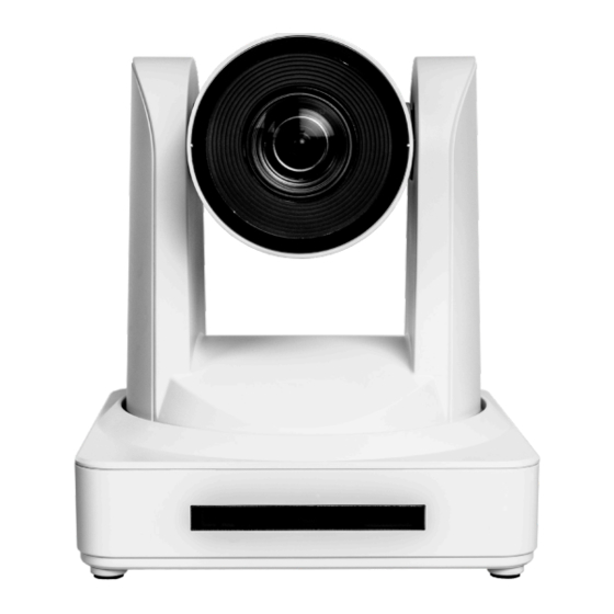
Panel Description Front (AT-HDVS-CAM-HDMI-WH shown) Back (AT-HDVS-CAM-HDMI-BK shown) RS-232 HDMI OUT DC 12V AT-HDVS-CAM-HDMI-BK 1. RS-232 3. HDMI OUT Connect included VISCA to RS-232 adapter here Connect to an HDMI device such as a video to control the camera with a third party software or conference codec or PC. -
Page 11: Installation
Installation Connection Instructions 1. Connect the included DC 12V power cable to the AT-HDVS-CAM-HDMI. 2. Connect the Ethernet cable to the LAN port on the back of the AT-HDVS-CAM-HDMI. 3. Connect the USB port of a conferencing system or USB extender such as AT-OME-EX-RX. 4. - Page 12 Installation Ceiling Mount installation To install the AT-HDVS-CAM-HDMI, 4 PA3X30 self-tapping screws, 4 PM3X6 screws, 4 screw stoppers, 1 1/4 20 UNC screw, the optional ceiling upper and lower covering plates, and the AT-HDVS-CAM-HDMI are needed. 1. Install the 4 screw stoppers in the ceiling. 2.
-
Page 13: Connection Diagram
Installation Connection Diagram Speakerphone C od Laptop Video Conferencing Codec S4 2 E- M A T- Laptop B- C B- C se T AT-HDVS-CAM-HDMI IT CH LT I-F AT-OME-MS42 Projector AT-HDVS-CAM-HDMI... -
Page 14: Device Operation
Device Operation Home Position “Home” position is a term that is used throughout this manual. When the AT-HDVS-CAM-HDMI is in home position, the camera is facing forward and has no tilt angle, as shown in the illustration below: RS-232 DC 12V AT-HDVS-CAM Front Left Side... -
Page 15: Field Of View
Device Operation Field of View When positioning the camera in a huddle room or similar area, it will be helpful to know the viewing area of the camera, based on a fixed target. The viewable area of the camera is called the linear field of view or sometimes referred to as the image plane. -
Page 16: Calculating Specific Values
Device Operation Calculating Specific Values In order to calculate custom values, this section introduces some trigonometric formulas which can be used to find the Linear Field of View (L), Distance (d), or the Angle of View (q). The derivation of each formula is beyond the scope of this manual. -
Page 17: Controlling The Camera
Device Operation Controlling the Camera The AT-HDVS-CAM-HDMI can be controlled using the included IR remote control, RS-232, TCP/IP, or through the webGUI. Refer to the WebGUI (page 17) for more information about accessing the webGUI. Tilt CAMERA SELECT The camera tilt range is approximately -45 degrees to +90 degrees. Use one of the following methods to adjust the camera tilt. -
Page 18: Tilt And Pan Combinations
Device Operation Tilt and Pan Combinations The webGUI provides a method for combining both tilt and pan motion. Note that this function is not available on the included IR Remote Control. webGUI (only) 1. Click Control in the side menu bar. 2. -
Page 19: Zoom
Device Operation Zoom The camera is provides a zoom factor up to 10x. Use one of the following methods to adjust the camera zoom. IR Remote Control webGUI CAMERA SELECT 1. Click Control in the side menu bar. • Locate the ZOOM rocker switch on the IR Remote Control. -
Page 20: Backlight Compensation (Blc)
Device Operation CAMERA SELECT Backlight Compensation (BLC) BLC is a feature which automatically adjusts the exposure control of the camera. When enabled, BLC will attempt to increase the ambient foreground light and “darken” any background light. For example, a subject standing in front of a window in the daytime, will produce a silhouetted effect. -
Page 21: Managing Presets
Device Operation Managing Presets Camera positions can be stored to local memory and recalled at a later time. Presets are stored and recalled using the included IR Remote Control. Up to 10 presets can be saved. Saving Presets 1. Set the camera in the desired position. 2. -
Page 22: Multiple Camera Control
Device Operation Multiple Camera Control There may be environments where more than one camera is being used. The included IR remote control unit provides a way to select and control up to four separate cameras. Assigning / Changing the Camera Address ID Before the IR remote control unit can be used to control different camera, each camera must be assigned an address ID. -
Page 23: Network Streaming
Device Operation Network Streaming This section covers video stream configuration, as well as RTMP publishing and RTP multicast. Refer to the Appendix (page 54) on how to configure streaming using VLC, Facebook Live, and YouTube Live. Video Stream Configuration 1. Login to the web server. 2. - Page 24 Device Operation Profile These options are only available when H.264 is selected. Profiles are a set of encoding processes for H.264. Profile Description Baseline Profile - Supports a limited set of processes and is designed to meet the needs of mobile devices. Main Profile - Supports a good number of processes and is typically used for devices such as set-top boxes.
- Page 25 Device Operation 5. Click the Save button to commit changes. 6. Click Reset in the side menu bar and click the Reboot button. Reboot button IMPORTANT: After settings have been updated, streams should be re-pulled and restarted to ensure best video quality. If the camera has been power-cycled, then it will be necessary to re-pull both RTMP and RTSP streams.
-
Page 26: Rtmp Publishing
Device Operation RTMP Publishing In order to for the stream to be pushed to live-streaming platforms, such as YouTube , Twitch , and others, follow the ™ ® procedure below. 1. Login to the web server. 2. Click Publishing in the side menu bar. RTMP Server, under the Encoding menu, should already be enabled. If not, please refer to Video Stream Configuration (page 23) for more information. -
Page 27: Rtp Multicast
Device Operation RTP Multicast In order to for the stream to be published to a multicast address, follow the procedure below. 1. Login to the web server. 2. Click RTP Multicast in the side menu bar. 3. Click the Enable checkbox to enable the Main Stream and/or Sub Stream. When enabled, the checkbox will contain a check mark. -
Page 28: Configuration And Management Interfaces
Configuration and Management Interfaces Web Server Main operation of the AT-HDVS-CAM-HDMI is handled through the built-in web server. In order to access the web server, the IP address of the unit must be known. Registration 1. Launch a desired web browser and enter the IP address of the AT-HDVS-CAM-HDMI in the address bar. 2. -
Page 29: Logging In
Configuration and Management Interfaces Logging In Before logging in to the web server, make sure the registration process has been completed. Refer to Registration (page 28) for more information. 1. Launch the desired web browser and enter the IP address of the AT-HDVS-CAM-HDMI in the address bar. 2. -
Page 30: Status Page
Configuration and Management Interfaces Status Page The Status page provides basic information about the AT-HDVS-CAM-HDMI, including the software version. Model The model of the unit. MAC Address The hardware MAC address of the unit. Serial Number The serial number of the unit. MCU Version The version of MCU firmware. -
Page 31: Firmware Page
Configuration and Management Interfaces Firmware Page Firmware Status - System The version of MCU firmware. Camera The version of camera firmware. Auto Focus The version of firmware which controls Auto-Focus. Firmware Update Update File Displays the file currently selected for the update process. Browse Click this button to select the desired firmware file for the update process. -
Page 32: System Page
Configuration and Management Interfaces System Page Information Device Name Displays the model of the unit. Device ID The device ID. Save Click this button to commit changes under this section. Cancel Click this button to abort changes under this section. Time Date Format Displays the file currently selected for the update process. - Page 33 Configuration and Management Interfaces Update Interval Click this drop-down list to select the time interval (in days), which the camera will poll the NTP server. This field is only active if the NTP check box is marked with a checkmark. Host URL Specify the NTP server address in this field.
-
Page 34: Network Page
Configuration and Management Interfaces Network Page Network Settings DHCP Switch between DHCP (ON) and static (OFF). IP Address Specify the IP address of the AT-HDVS-CAM-HDMI in this field. This field is only active if DHCP is set to OFF. Subnet Specify the IP subnet mask in this field. - Page 35 Configuration and Management Interfaces Port Settings Enter the required port number in each of these fields. Each field contains the default port settings. Available values are from 0 to 65535. Save Click this button to commit changes under this section. Cancel Click this button to abort changes under this section.
-
Page 36: User Page
Configuration and Management Interfaces User Page User User Name Enter the desired user name in this field. New password Enter the new password in this field. Re-enter password Confirm the new password by entering it in this field. Save Click this button to commit changes under this section. Cancel Click this button to abort changes under this section. -
Page 37: Encoding Page
Configuration and Management Interfaces Encoding Page Video Encoding RTSP Server Enable / disable the RTSP protocol. RTMP Server Enable / disable the RTMP protocol. Main Stream / Sub Stream These settings affect the main stream, which is the primary video feed and provides the highest quality video. This stream is used by a digital recorder when saving footage to hard disk. - Page 38 Configuration and Management Interfaces Compressed Format Click this drop-down list to select the desired profile. Profile Description Baseline Profile - Supports a limited set of processes and is designed to meet the needs of mobile devices. Main Profile - Supports a good number of processes and is typically used for devices such as set-top boxes.
-
Page 39: Publishing Page
Configuration and Management Interfaces Publishing Page Main Stream / Sub Stream These settings affect the main stream, which is the primary video feed and provides the highest quality video. Sub Stream is the secondary video feed and provides a lower quality video stream. This stream is used to stream video to computers and mobile devices. -
Page 40: Rtp Multicast Page
Configuration and Management Interfaces RTP Multicast Page Main Stream / Sub Stream These settings affect the main stream, which is the primary video feed and provides the highest quality video. Sub Stream is the secondary video feed and provides a lower quality video stream. This stream is used to stream video to computers and mobile devices. -
Page 41: Reset Page
Configuration and Management Interfaces Reset Page Factory Reset Factory Reset Click this button to factory-reset the AT-HDVS-CAM-HDMI. Reboot Reboot Click this button to reboot/power-cycle the AT-HDVS-CAM-HDMI. AT-HDVS-CAM-HDMI... -
Page 42: Picture Page
Configuration and Management Interfaces Picture Page Image preview Picture Settings Bright Click and drag this slider to adjust the picture brightness between a value of 0 and 14. Larger values produce a brighter image. The default setting is 6. Contrast Click and drag this slider to adjust the picture contrast between a value of 0 and 14. - Page 43 Configuration and Management Interfaces Saturation Click this drop-down list to select the desired saturation value. Available values are between 60% and 200% in increments of 10. Larger values will produce and image with a higher color contrast. The default setting is 100%. WB Mode Click this drop-down list to select the desired white balance setting.
-
Page 44: Focus Page
Configuration and Management Interfaces Focus Page Image preview Focus Settings Focus Mode Click this drop-down list to select the desired focus mode. Focus Mode Description Auto Automatically adjusts focus based on the captured image. Manual Permits manual focus control. OnePush When selected, this option will adjust the focus based on the currently captured image. -
Page 45: Exposure Page
Configuration and Management Interfaces Exposure Page Image preview Exposure Settings Mode Click this drop-down list to select the desired mode. Mode Description Auto Automatically adjusts the exposure, based on available light. Manual Permits manual exposure control. When selected, the following options will be available: Iris, Shutter, and Gain. - Page 46 Configuration and Management Interfaces Mode Description Aperture Automatic Exposure (AAE). When selected, this option will measure the incoming light and automatically adjust the shutter speed based on the selected iris (aperture) setting. Bright When selected, a Bright slider will be displayed. The larger the value, the brighter the image.
-
Page 47: Style Page
Configuration and Management Interfaces Style Page Image preview Style Style Click this drop-down list to select the desired image style. Style is an image preset, which produces a desired look. Available options are: Default, Normal, Clarify, Bright, and Soft. AT-HDVS-CAM-HDMI... -
Page 48: Osd Page
Configuration and Management Interfaces OSD Page Image preview OSD Settings Show Title Click this check box to display the device name in the upper-left corner (default position) of the screen. When enabled, the check box will display a check mark. To change the device name, refer to the System > Information > Device Name on the System Page (page 33). -
Page 49: Video Out Page
Configuration and Management Interfaces Video Out Page Video Out Video Out Format Click this drop-down list to select the desired output resolution. Available resolutions are listed in the table below. Format 1080P60 720P60 1080P50 720P50 1080P30 1080P59.94 1080P25 1080I59.94 1080I60 1080P29.97 1080I50 720P59.94... -
Page 50: Control Page
Configuration and Management Interfaces Control Page Image preview Camera Control Refer to Controlling the Camera (page 18) for more information. Pan-Tilt-Zoom Click these arrows to adjust the pan, tilt, and zoom of the camera. Focus Mode Click this drop-down list to select the desired focus mode. AT-HDVS-CAM-HDMI... -
Page 51: Ir Remote And Osd
IR Remote and OSD IR Remote Control The AT-HDVS-CAM-HDMI comes with an IR remote control for full control of the camera and use of the OSD menu. Power Toggle the camera on and off with the power button. Press and hold for 3 seconds to place the camera into standby mode. - Page 52 IR Remote and OSD OSD Cont. Camera Exposure Mode Auto Bright Manual Bright 0 to 23 IRIS F1.8 F1.8 F1.8, F2.0, F2.4, F2.8, F3.4, F4.0, F4.8, F5.6, F6.8, F8.0, F9.6, F11, Close Shutter 1/100 1/100 1/25, 1/30, 1/50, 1/60, 1/90, 1/100, 1/120, 1/180, 1/250, 1/325, 1/500, 1/1000,...
-
Page 53: Remote Functions
IR Remote and OSD OSD Cont. P/T/Z Speed By Zoom ON, OFF Zoom Speed 1 to 8 Acc Curve Slow Slow, Fast Version MCU Version X.X.X 20YY-MM-DD Camera Version X.X.X 20YY-MM-DD AF Version X.X.X 20YY-MM-DD Ethernet IP Address XXX.XXX.XXX.XXX e.g. 10.20.20.233 Subnet Mask XXX.XXX.XXX.XXX e.g. -
Page 54: Appendix
Appendix Using VLC Player This section provides step-by-step instructions on how to display a stream using the VideoLAN VLC media player. Before proceeding, make sure that both the Main Stream and Sub Stream are properly configured. Refer to the User Manual for more information. - Page 55 Appendix 5. Click the Play button to begin streaming. VLC will begin buffering the stream. Note that it may take a few moments for the network stream to be displayed. AT-HDVS-CAM-HDMI...
-
Page 56: Using Facebook Live
Appendix Using Facebook Live This section provides step-by-step instructions on how to display a stream using Facebook Live. Before proceeding, make sure that both the Main Stream and Sub Stream are properly configured. Refer to the User Manual for more information. - Page 57 Appendix 5. Go to the Publishing page of the AT-HDVS-CAM-HDMI web server. 6. Paste the contents from the Server URL field, on Facebook, to the Host Address field in the camera web interface. Note that the contents of the Facebook Server URL field can be placed under the Main Stream or Sub Stream.
- Page 58 Appendix 10. Paste the contents from the Stream Key field, on Facebook, to the Stream Key field in the camera web interface. Make sure that the contents are pasted into the correct field. Refer to the User Manual for the AT- HDVS-CAM-HDMI for information on Main Stream and Sub Stream configuration.
-
Page 59: Using Youtube Live
Appendix Using YouTube Live This section provides step-by-step instructions on how to display a stream using YouTube Live. Before proceeding, make sure that both the Main Stream and Sub Stream are properly configured. Refer to the User Manual for more information. - Page 60 Appendix 4. The next screen will provide the option of selecting a Built-in webcam or Streaming software. Click the Go button next to Streaming software. 5. Set the desired settings in the Edit stream dialog box. 6. Click the SAVE button to commit changes. AT-HDVS-CAM-HDMI...
- Page 61 Appendix 7. Click the COPY button, next to the Stream URL field. 8. Go to the Publishing page of the AT-HDVS-CAM-HDMI web server. AT-HDVS-CAM-HDMI...
- Page 62 Appendix 9. Paste the contents from the Stream URL field, on YouTube Live, to the Host Address field in the camera web interface. Note that the contents of the YouTube Live Stream URL field can be placed under the Main Stream or Sub Stream.
- Page 63 Appendix 12. Paste the contents from the Stream key field, on YouTube Live, to the Stream Key field in the camera web interface. Make sure that the contents are pasted into the correct field. Stream Key 13. Click the Save button to commit changes. 14.
-
Page 64: Specifications
Appendix Specifications Video Signal HDMI 1920x1080p@60/59.97/50/30/29.97/25 Hz 1920x1080i@60/59.94/50 Hz 1280x720p@60/59.94/50 Hz Color Space YUV, RGB Chroma Subsampling 4:4:4, 4:2:2, 4:2:0 Streaming Video Compression H.264 / H.265 Protocol TCP, UDP, RTMP, RTSP Bitrate 46 kbps - 40960 kbps Compression Profiles BP, MP, HP Bitrate Control Multi-Stream Main Stream / Sub Stream (simultaneous stream output) - Page 65 Appendix Pan Rotation ± 170° Tilt Rotation -30° ~ +90° Pan Control Speed 0.1 - 180° / sec Tilt Control Speed 0.1 - 80° / sec Preset Speed Pan: 60° / sec, Tilt: 30° / sec Preset Number 255 (10 presets using the included IR remote control) Connectors HDMI OUT 1 - Type A, 19-pin, female...
- Page 66 Toll free US International atlona.com 877.536.3976 41.43.508.4321 • • 35287-R3...
Need help?
Do you have a question about the Atlona AT-HDVS-CAM-HDMI and is the answer not in the manual?
Questions and answers