Table of Contents
Advertisement
Quick Links
Assembly Instructions
AC•THOR®i Assembly Instructions, Version 210326
1
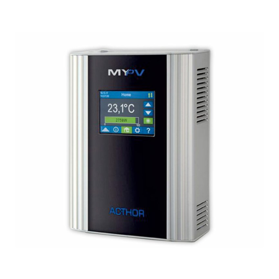
AC•THOR
Photovoltaic Power Manager
In addition to these assembly instructions, the
current version of the
for the device is available at www.my-pv.com.
Wiring diagrams at the end of the document.
The following device key is required for online
registration of the unit. Keep it safe!
®
i
Operating instructions
equired for cloud service
R
at www.my-pv.live
Device key
:
registration
Advertisement
Table of Contents

Subscribe to Our Youtube Channel
Related Manuals for MYPV AC-THOR i

Summary of Contents for MYPV AC-THOR i
- Page 1 Assembly Instructions ® AC•THOR Photovoltaic Power Manager In addition to these assembly instructions, the current version of the Operating instructions for the device is available at www.my-pv.com. Wiring diagrams at the end of the document. The following device key is required for online registration of the unit.
-
Page 2: Manufacturer
Manufacturer my-PV GmbH Teichstraße 43, 4523 Neuzeug, Austria info@my-pv.com www.my-pv.com.au Australian & New Zealand Distributor Energy Smart Water Pty Ltd ABN 65 161 756 690 2/11 Dalkeith Drive, Dromana Vic 3936, Australia esw.net.au | +61 3 9939 6722 | info@esw.net.au AC•THOR®i Assembly Instructions, Version 210326... -
Page 3: Table Of Contents
Contents Manufacturer ................... 2 Australian & New Zealand Distributor ..........2 Operation manual ..............5 Intended use ................5 Scope of supply ............... 6 Safety instructions ..............7 Connections overview ............. 9 Mounting ................9 Electrical connection ............. 11 7.1. Connecting temperature probes ........ - Page 4 Wiring diagrams ..............20 15.1. AC•THOR®i - Wiring the control side ......20 Power Meter – connection via router ......20 Power Meter – connection without router ....21 Power Meter – connection without router via powerline ..............22 Control by inverter or battery management ....23 Control by the energy management system ....
-
Page 5: Operation Manual
1. Operation manual In addition to these assembly instructions, the current version of the Operating instructions for the device is available at www.my-pv.com. Wiring diagrams at the end of the document. 2. Intended use The electronic AC•THOR®i Photovoltaic-Power-Manager (in the following, AC•THOR®i for short) is designed for operating resistive loads such as electric immersion heater elements, electric boilers, electric convectors, electric heating mats or infrared panels. -
Page 6: Scope Of Supply
Installation in rooms with high levels of humidity must comply with the relevant regulations. The ACTHOR has an ambient temperature rating of 0°C -40°C. If installed outdoors it must be able to function within this temperature range and be located in a shaded position inside an IP55 rated waterproof cabinet which allows airflow around the unit. -
Page 7: Safety Instructions
Optional Accessories Available (not included) my-PV Power Meter my-PV digital temperature sensor (cable length 5 m) with 8-pin plug 4. Safety instructions Installation must be carried out by a licensed electrician in accordance with AS/NZS 3000. For water heating applications compliance with AS/NZS 3500 is required. - Page 8 All connected devices must be operated with phase and neutral conductor. Never connect three phase loads without neutral conductor! Otherwise this may cause damage to the AC•THOR®i or to the other loads connected to it. Only the supplied plugs must be used for connection to the AC•THOR®i.
-
Page 9: Connections Overview
5. Connections overview 230VAC 3.000 W max. Sensors 240VAC 3.600 W max. 6. Mounting 1. Remove the wall bracket from the rear of the AC•THOR®i unit. To do this, slide the lock underneath to the right. AC•THOR®i Assembly Instructions, Version 210326... - Page 10 2. Then fix the wall bracket to the wall with three screws. Three screws and three wall-plugs are supplied. If the screws supplied are not suitable for the substrate, suitable screw must be obtained. 3. To fix it to the wall bracket, the AC•THOR®i is suspended in the wall bracket by the two long slots on top and then fixed in place by locking it underneath (slide to the left).
-
Page 11: Electrical Connection
Do not immerse my-PV temperature sensor(s) directly in Water. Use a thermowell! For mains leads, use a cable duct of 60 mm depth. The cut-out measures 130 x 60 mm. 7. Electrical connection The AC•THOR®i is controlled by external signal sources by way of IP protocol using a standard Ethernet RJ45 cable. -
Page 12: Connecting Temperature Probes
The solar diverter (AC•THOR®i) circuit shall be protected by a 30 mA Type AC RCD installed in accordance with AS/NZS 3000. An isolating switch in accordance with clause 4.8.2.3 AS/NZS 3000:2018 shall be installed for the water heater. Where more than one circuit can supply the water heater, a warning sign shall be installed within the installation switchboard that the solar diverter circuit originates, and on the water heater. -
Page 13: Electrical Connection For Multiple Units
If more than one probe is used, the cores can also be connected externally in parallel. 7.2. Electrical connection for multiple units All devices should be connected to appropriate AC circuits. Note that each AC•THOR®i takes up to 3.6 kW power (with relay output up to 7.2 kW). It makes sense to divide this between the phases on the grid. -
Page 14: Maintenance
menu guide, and settings are located in the Operating Instructions for the unit. The current version is available at www.esw.net.au 9. Maintenance Do not attempt to open the AC•THOR®i. The device does not contain any parts that may be repaired by the user. In the event of a fault, please contact Energy Smart Water on 1800 433 254 or email techsupport@esw.net.au Never splash water on or in the unit! -
Page 15: Disposal
11.Disposal Packaging material must be either stored or disposed of as appropriate. Dispose of the AC•THOR®i at the end of its service life according to the statutory regulations. 12.Warranty 12.1. Warranty – General This warranty is given by Energy Smart Water Pty. Ltd., 2/11 Dalkeith Drive, Dromana Vic 3936, Australia, ABN 65 161 756 690 for installations in Australia and New Zealand only. -
Page 16: Warranty Exclusions
building codes, occupational health, safety & welfare regulations, and other State or Federal statutory regulations. Where a failed product is replaced under this warranty, the balance of the original warranty period will remain effective. The replacement does not carry a new warranty. This warranty extends to the original purchaser and subsequent owners, but only while the product remains at the site of the original installation. -
Page 17: How To Make A Warranty Claim
Where the product is located in a position that does not comply with the installation instructions or relevant statutory requirements. Where the product is moved or reinstalled at a new location. Where the connection, attachment, integration or general association of other equipment or parts not instructed by this manual which either directly or indirectly affect the performance or operation of this equipment. -
Page 18: Eu Declaration Of Conformity
The Energy Smart Water warranty is in addition to any rights and remedies that you may have under the Australian Consumer Law. 13.EU declaration of conformity my-PV GmbH, Teichstraße 43, 4523 Neuzeug, Austria hereby declares that the products of the product AC•THOR®i comply with the following Directives and standards: EN 55014-1, EN 55014-2, EN 60730-1, EN 62233, EN 61000-3-2, EN 61000-3-3... -
Page 19: Technical Specifications
14.Technical specifications Mains voltage 230/240 V, 45-65 Hz Outputs 0 to 230 VAC 3000 W max. 0 to 240 VAC 3600 W max. pure sine wave Relay output 1 x NC/NO 20 V AC 100 mA min. 230/240 V AC 16 A max. Mains connection 3-phase with neutral conductor Safeguarding... -
Page 20: Wiring Diagrams
15.Wiring diagrams For installations in 240 V grids instead of 3kW loads 3.6kW NOTE: loads are allowed! 15.1. AC•THOR®i - Wiring the control side Power Meter – connection via router Establishing the automatic connection via router may take as much as a minute! AC•THOR®i Assembly Instructions, Version 210326... -
Page 21: Power Meter - Connection Without Router
Power Meter – connection without router AC•THOR®i Assembly Instructions, Version 210326... -
Page 22: Power Meter - Connection Without Router Via Powerline
Power Meter – connection without router via powerline AC•THOR®i Assembly Instructions, Version 210326... -
Page 23: Control By Inverter Or Battery Management
Control by inverter or battery management AC•THOR®i Assembly Instructions, Version 210326... -
Page 24: Control By The Energy Management System
Control by the energy management system AC•THOR®i Assembly Instructions, Version 210326... -
Page 25: Ac•Thor®I Wiring Applications
15.2. AC•THOR®i Wiring applications Operating mode M1: Hot water 3 kW AC•THOR®i Assembly Instructions, Version 210326... -
Page 26: Operating Mode M2: Hot Water Stratification Charge
Operating mode M2: Hot water stratification charge AC•THOR®i Assembly Instructions, Version 210326... -
Page 27: Operating Mode M3: Hot Water 6 Kw
Operating mode M3: Hot water 6 kW AC•THOR®i Assembly Instructions, Version 210326... -
Page 28: Operating Mode M4: Hot Water + Heat Pump
Operating mode M4: Hot water + heat pump AC•THOR®i Assembly Instructions, Version 210326... -
Page 29: Operating Mode M5: Hot Water + Space Heating
Operating mode M5: Hot water + space heating AC•THOR®i Assembly Instructions, Version 210326... -
Page 30: Operating Mode M6: Space Heating
Operating mode M6: space heating AC•THOR®i Assembly Instructions, Version 210326... -
Page 31: Connecting Three-Phase Heating Elements
Connecting three-phase heating elements AC•THOR®i Assembly Instructions, Version 210326...
Need help?
Do you have a question about the AC-THOR i and is the answer not in the manual?
Questions and answers