Table of Contents
Advertisement
Quick Links
Advertisement
Table of Contents

Related Manuals for Arexx AAR-04


Summary of Contents for Arexx AAR-04
- Page 1 AREXX ARDUINO ROBOT MANUAL: AAR-04 © AREXX - The Netherlands V062012 - 1 -...
-
Page 2: Table Of Contents
9.3 Main Board - Bottom View 9.4 Schematics AAR NOTICE! AAR is a trademarks of AREXX, The Netherlands and JAMA, Taiwan. AREXX and JAMA are registered trademarks All rights reserved. Reprinting any of this instruction manual without our permission is prohibited. -
Page 3: Product Description Aar
As a successor for the ASURO-robot, which has been programmed in C-language we now designed the AREXX Arduino robot. The new robot resembles its predecessor ASURO, but in combination with an „open source“- programming language Arduino programming the system will be much easier. - Page 4 1.3. Precautions 1. Attention! You must read this manual before supplying power to any of the terminals! Incorrect connections may damage the hardware. 2. Attention! Please check the pin function diagram carefullyBe careful in wiring the circuitry. Incorrect connections may damage the modules. Respect the correct power supply’s polarity.
-
Page 5: Arduino General Description
2. ARDUINO General Description 2.1. Who or what is ARDUINO? Arduino is an open source- single board microcontroller, which pro- vides an easy access to programming, microcontrollers and project- platforms for interactive objects for artists, designer, hobbyists and others. The Arduino-platform has been based on an Atmel’s ATmega168 or ATmega328 microcontroller. - Page 6 2.2 Microcontrollers! 2.2.1. Applications A microcontroller (sometimes abbreviated µC, uC or MCU) is a small computer on a single integrated circuit containing a processor core, memory, and programmable input/output peripherals. Program memory and a small amount of data memory (RAM) is also often included on chip.
- Page 7 2.3. Power Consumption and Speed Some microcontrollers may operate at clock rate frequencies as low as 4 kHz, for low power consumption (milliwatts or micro- watts). They will generally have the ability to retain functionality while waiting for an event such as a button press or other interrupt; power consumption while sleeping (CPU clock and most peripherals off) may be just nanowatts, making many of them well suited for long lasting battery applications.
- Page 8 Microcontrollers were originally programmed only in assembly language, but various high-level programming languages are now also in common use to target microcontrollers. These languages are either designed specially for the purpose, or versions of general purpose languages such as the C programming language. Microcon- troller vendors often make tools freely available to make it easier to adopt their hardware.
- Page 9 In addition to the converters, many embedded microprocessors in- clude a variety of timers as well. One of the most common types of timers is the Programmable Interval Timer (PIT). A PIT just counts down from some value to zero. Once it reaches zero, it sends an in- terrupt to the processor indicating that it has finished counting.
-
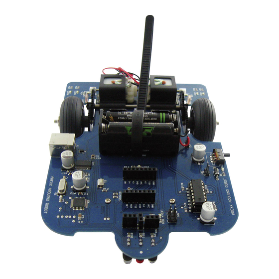
Page 10: Arexx Arduino Robot
AREXX ARDUINO ROBOT Fig. :AAR PCB 3.1 ARDUINO ROBOT Block diagram 1. Connector plug for the battery compartment. (Be careful to check for the correct polarity!) 2. On/Off-Switch for the Robot. 3. Status-LED: signaling that the robot is being supplied from the power supply. - Page 11 USB-plug. This option is quite comfortable for testing and programming. Rather comfortable in this robotic concept are the connector plugs, which allow you to insert your own extension modules or the AREXX- extension modules from the ASURO-series. - 11 -...
-
Page 12: Arduino Software
BACKGROUND-INFORMATION FOR THE ARDUINO SOFTWARE Arduino Software belongs to the Open Source-category and is uni- versally available to all, including the source codes for the program- ming platform. The Arduino programming platform has been equipped with a text- editor, a message window and a text-console. The programming platform may directly contact the AAR for communication and allows us to easily transfer programs into the processor. -
Page 13: The Arexx Arduino Robot (Aar)
4. Getting Started 4.1. Download and installation of Arduino’s Software Install the Arduino software (version 1) from the CD we are sure this will work. Later you also can go to the ARDUINO website and download the latest version from this site. IMPORTANT: using different versions of the ARDUINO Software and different version of the application software may give some problems. -
Page 14: Aar Hardware
4.4. AAR hardware 4.4.1. Installing the batteries The robot has been designed for a power supply filled with four 1,5V AAA-cells. If you prefer to use rechargeable batteries the jumper JP4 should be installed as a bridge to prepare the system for a lower voltage of the rechargeable batteries (see fig. -
Page 15: Arduino Software
4.5 ARDUINO software 4.5.1 Programming the Robot with Arduino Programs. Connect the robot by USB-cable to your PC. As soon as the robot has been connected to an USB-port the Ar- duino-system does not really need an extra battery or other power supply. -
Page 16: Selecting The Correct Com-Port
Fig. 4a Program Blink Fig. 4b Select Board At this stage we will have to select the correct Arduino-board at the menu-entryTools>Board> Arduino Duemilanove or Nano w/Atme- ga328 (see fig. 4b) 4.5.3 Select Compoort The next step defines the correct COM-port for the Arduino-interface. The correct COM-interface (or COM-port) for the robot is COM 12. -
Page 17: Program Transfers To The Arduino Robot
PC, connect the battery-compartment or power supply and start the robot. For further information and downloads we invite you to visit one of the forums at the websites: www.arexx.com --> Forum www.roboternetz.de --> Forum - 17 -... -
Page 18: Background-Information To The H-Bridge Circuits
5. Background-information to the H-Bridge circuits A H-bridge is an electronic circuit which allows us to reverse the polarity of a device (such as a DC-motor) by controlling four switches. These H-bridges will often be found in robotics to control a motor rotation in two opposite directions. - Page 19 In the driver stage we may identify the DC-motor M. The preamplifier of the driver circuit is being simulated by resistor R14. This resistor will pull the base-ports of transistors TR6 and TR5 to 0V, which results in a condition in which only the right-sided branch is conducting a significant current.
- Page 20 The 3V-power supply is an ideal condition for a robot with a battery- pack of only 2 cells. The PNP-transistors however cannot easily be integrated in an IC such as the L293D. An IC however has other advantages such as reliability, protection against bad circuitry and reduced PCB-area and low weight.
-
Page 21: Odometry
Odometry This chapter has been devoted to some interesting application-con- cepts for the AAR-robot. The ideas refer to studies and art-projects. Maybe developing such software will inspire us in programming micro-controllers. Line-seekers, color-lovers and color-haters Light-sensitive sensors will allow us to program robots to be- have like line-seekers, color-lovers or color-haters. - Page 22 Complex Line-seekers Line-seeking and line-following robots usually will need a light source such as a LED and twi or more light sensors. These devices allow the system to identify a line and follow the track. Initially the robot may need a special search pattern routine to find a line. The pattern may consist of a strategy to follow a spiral pattern with a gradually increasing radius from the starting point.
- Page 23 Experienced programmers are aware of the complexity and design requirements of a program which needs to serve the problems of a line-follower with several differentiated color and sound dependen- cies. Programmers will have to design a program with a hierarchical set of numerous functions.
-
Page 24: Programming A Boot-Loader
7. Programming a Boot-loader ATTENTION! The described road-map in this chapter requires programming experience! You will be able to upload an Arduino-bootloader into the micro- controller: for instance with the help of STK500. In order to transfer any program, which has been written in Arduino language, into the Atmega micro-controller the Atmega-processor will have to be equipped with a special Arduino-boot-loader. - Page 25 APENDIX - 25 -...
- Page 26 Partlist Part Value Package 18pF 0805 18pF 0805 0.1uF C0805K 0,1uF 0805 0,1uF 0805 470uF CPOL-USF 0,1uF 0805 4,7uF 1206 0,1uF 0805 0,1uF 0805 0,1uF 0805 0,1uF 0805 0,1uF 0805 470uF CPOL-USF 470uF CPOL-USF 470uF CPOL-USF MBR0520 SOD-123 1N4001 DO41-10 FT232RL SSOP28 L293D...
- Page 27 Part Value Package LED8 LEDCHIP-LED0805 LED9 LEDCHIP-LED0805 LED10 LEDCHIP-LED0805 LED11 LEDCHIP-LED0805 LED12 LEDCHIP-LED0805 LED13 LEDCHIP-LED0805 LED14 LEDCHIP-LED0805 LED16 LEDCHIP-LED0805 LED17 LEDCHIP-LED0805 LED18 LEDIRL80A 16MHz CRYSTALHC49UP R-US_R0805 R-US_R0805 R-US_R0805 R-US_R0805 R-US_R0805 R-US_R0805 R-US_R0805 R-US_R0805 R-US_R0805 R-US_R0805 R-US_R0805 R-US_R0805 R-US_R0805 R-US_R0805 R-US_R0805 R-US_R0805 R-US_R0805 R-US_R0805...
- Page 28 MAIN PCB TOP - 28 -...
- Page 29 MAIN PCB BOTTOM - 29 -...
- Page 30 C. CIRCUIT AAR - 30 -...
Need help?
Do you have a question about the AAR-04 and is the answer not in the manual?
Questions and answers