Table of Contents
Advertisement
Quick Links
Operating Manual BMGZ710
and BMGZ710.PNET
Robust evaluation unit for conveyor belt scales, with
optional PROFNET interface
Document Version
2.00
Published / Author
04/2021
NS
Firmware Version BMGZ710
0.2.7
Firmware Version BMGZ710.PNET
0.5.4
Diese Bedienungsanleitung ist auch in Deutsch erhältlich.
Bitte kontaktieren Sie Ihre nächstgelegene FMS Vertretung.
© by FMS Force Measuring Systems AG, CH-8154 Oberglatt – All rights reserved.
Advertisement
Table of Contents

Related Manuals for FMS BMGZ710

Summary of Contents for FMS BMGZ710
- Page 1 2.00 Published / Author 04/2021 Firmware Version BMGZ710 0.2.7 Firmware Version BMGZ710.PNET 0.5.4 Diese Bedienungsanleitung ist auch in Deutsch erhältlich. Bitte kontaktieren Sie Ihre nächstgelegene FMS Vertretung. © by FMS Force Measuring Systems AG, CH-8154 Oberglatt – All rights reserved.
-
Page 2: Table Of Contents
Scope of delivery ..........................5 Order code for evaluation unit ......................6 INSTALLATION ............................7 Electrical connection (see installation instructions for the FMS measuring roller) ......8 OPERATION AND SURFACE ......................... 11 Navigation, quick start ........................11 CONFIGURATION ............................ 14 Plant parameters .......................... - Page 3 Operating Manual BMGZ710 and BMGZ710.PNET TECHNICAL DATA BMGZ710 ........................ 36 10.1 Specification PROFINET interface ....................36 20.04.2021...
-
Page 4: Safety Instructions
Operating Manual BMGZ710 and BMGZ710.PNET 2 Safety instructions All safety, operating, and installation instructions given here serve to ensure that the device functions properly. They must be observed in all circumstances to ensure the safe operation of systems. Failure to comply with the safety instructions or use of the devices outside of the specified performance characteristics may endanger the safety and health of persons. -
Page 5: Product Information
Operating Manual BMGZ710 and BMGZ710.PNET 3 Product information 3.1 System configuration Illustration 1: Measuring roller and evaluation unit BMGZ700_BA_Manual.ai 3.2 Product description The evaluation units in the BMGZ700 series are designed to meet the demanding conditions of applications in mobile and stationary conveyor systems. The illuminated graphical display shows the current flow rate, the daily amount, the total amount, and the belt speed. -
Page 6: Order Code For Evaluation Unit
Operating Manual BMGZ710 and BMGZ710.PNET Evaluation unit; for the .K version, the evaluation unit is preinstalled in the control cabinet Not included in the delivery: Power supply unit, installation materials Also available: Measuring roller, connection cable from evaluation unit to measuring roller (specify length), M12 d-coded Ethernet cable, or RJ45 patch cable for web browser. -
Page 7: Installation
Operating Manual BMGZ710 and BMGZ710.PNET 4 Installation Several versions of the evaluation unit are available. Illustration 3: BMGZ710.W Wall mount BMGZ700_BA_Manual.ai Unscrew the 4 screws on the cover with the membrane control panel and display The cover can now be opened The housing is screwed on through the 4 holes in the bottom of the housing Illustration 4: BMGZ710.S Panel mount... -
Page 8: Electrical Connection (See Installation Instructions For The Fms Measuring Roller)
The cabinet is screwed on through the 4 holes in the back wall Use the rubber mounts if the system experiences vibrations 4.1 Electrical connection (see installation instructions for the FMS measuring roller) The connection between the measuring roller and the evaluation unit must use the 8- core twisted-pair cable (min. - Page 9 Operating Manual BMGZ710 and BMGZ710.PNET Illustration 7: Terminal assignment BMGZ710 BMGZ700_BA_Manual.ai 20.04.2021...
- Page 10 Operating Manual BMGZ710 and BMGZ710.PNET Illustration 8: Connection cable, measuring roller side BMGZ700_BA_Manual.ai 20.04.2021...
-
Page 11: Operation And Surface
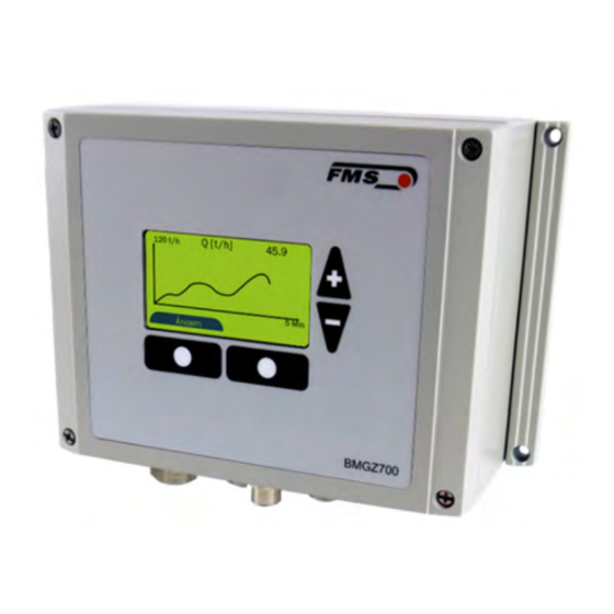
Operating Manual BMGZ710 and BMGZ710.PNET 5 Operation and surface Illustration 9: View of device BMGZ700_BA_Manual.ai The assignment of the softkeys may vary. The saved functions are shown on the display. 5.1 Navigation, quick start The menu is divided into two levels... - Page 12 Operating Manual BMGZ710 and BMGZ710.PNET Levels, navigation Levels Navigation Display HOME Home Histogram Zero setting Batch 20.04.2021...
- Page 13 Operating Manual BMGZ710 and BMGZ710.PNET Detail CONFIGURATION PARAMETER 20.04.2021...
-
Page 14: Configuration
Operating Manual BMGZ710 and BMGZ710.PNET 6 Configuration 6.1 Plant parameters The plant parameters directly affect the weighing results. Plant parameters Parameter Unit Selection Default Min. Max. Offset [Digit] -32768 32767 Gain Belt length 5000 Diameter [mm] 1000 Pulse Distance [mm]... - Page 15 Operating Manual BMGZ710 and BMGZ710.PNET Parameter Name Description Belt length The unrolled length of the conveyor belt is saved under this parameter. This value is required for taring. Unit Min. Max. 5000 Default Increment The diameter of the centre roller is saved under this parameter Diameter (see measuring roller nameplate).
-
Page 16: Operating Parameters
Operating Manual BMGZ710 and BMGZ710.PNET Parameter Name Description Nominal force Nominal force of the force senors. This value is indicated on the label of the measuring roller and the labels of each force sensor. See measuring roller nameplate. Unit Min. -
Page 17: Description Of Operating Parameters
Operating Manual BMGZ710 and BMGZ710.PNET 6.2.1 Description of operating parameters Operating parameters Name Description Pulse output The pulse output of the BMGZ700 emits a pulse after a certain integrated weight has been exceeded. The weight corresponding to one pulse is stored under this parameter. - Page 18 Operating Manual BMGZ710 and BMGZ710.PNET Operating parameters Name Description Scaling output Here, you can define the flow rate that generates the maximum output signal (10 V or 20 mA) at the analogue outputs. The resolution is 12 bits. Unit Min.
-
Page 19: System Parameters
Operating Manual BMGZ710 and BMGZ710.PNET 6.3 System parameters System parameters Parameter Unit Selection Default Min. Max. Language German, German English Filter display Date format DD.MM.Y DD.MM.YYYY YYY, MM.DD.Y Time / date 00:00 23:59 01.01.202 31.12.2099 IP address 192.168.0.90 Subnet mask 255.255.255.0... - Page 20 Operating Manual BMGZ710 and BMGZ710.PNET System parameters Name Description Time / date The evaluation unit has a built-in real-time clock (RTC). To configure the time, the current time and date can be entered into this parameter. This information is stored in the alibi memory with the corresponding batch.
-
Page 21: Service
Operating Manual BMGZ710 and BMGZ710.PNET 6.4 Service Service Parameter Unit Display A/D values raw Digit Raw value DMS raw Raw value Travel Raw value minus offset Force Calculated Belt kg/m Weight Digital inputs: Status: 0 = inactive; 1 = active... -
Page 22: Digital Inputs
Operating Manual BMGZ710 and BMGZ710.PNET start zero settubg or adjust offset manually. 4 Impulse output too fast. The impulse output is no longer correct. The load is higher that the output can indicate. Reduce speed or load or enhance the... -
Page 23: Digital Outputs
Operating Manual BMGZ710 and BMGZ710.PNET speed value for the calculation. However, the evaluation electronics only integrates the weight as long as this digital input 3 "Belt running" is active, otherwise not. This function is practically not used in practice, since the automatic belt speed detection is used. -
Page 24: Standard Procedures
Operating Manual BMGZ710 and BMGZ710.PNET 7 Standard procedures 7.1 Taring (zero setting) Taring ensures that no weight is integrated when the belt is idling to avoid weighing errors. The weight of the belt and the measuring roller are subtracted from the measurement. -
Page 25: Calibrating
Operating Manual BMGZ710 and BMGZ710.PNET Setting the “taring” digital input begins the recalculation of the offset. This is described in Section 3.3 Taring (zero setting). The “taring active” digital output is set until the procedure is completed or aborted. If the “taring” input is reset before the remaining time has elapsed, the procedure is aborted, the “taring active”... -
Page 26: Manual Batch Weighing
Operating Manual BMGZ710 and BMGZ710.PNET 7.3 Manual batch weighing Illustration 12: Manual weighing of a batch Start the conveyor belt without any load Press the “Reset” softkey on the home screen The batch amount is set to zero The batch counter is incremented Run the desired amount over the conveyor system. -
Page 27: Configuration Via Web Interface
Operating Manual BMGZ710 and BMGZ710.PNET 8 Configuration via web interface You can configure the evaluation unit using a web browser (Internet Explorer 7 or higher). To do this, either connect the web guiding controller to an Ethernet network or connect it directly to a PC. - Page 28 Operating Manual BMGZ710 and BMGZ710.PNET Illustration 14: Status of LAN connection Illustration 15: Status of LAN connection Select “Properties” The “Local Area Connection Properties” window will open Select “Internet Protocol Version 4 (TCP/IPv4)”. Select “Properties”. The corresponding window will open.
- Page 29 Operating Manual BMGZ710 and BMGZ710.PNET Illustration 16: Internet protocol properties Select “Use the following IP address:” Enter the PC address (e.g. 192.168.000.1) In the subnet mask, enter: 255 255 255 000 Close the window with “OK”. Close all other windows The computer is now ready to communicate with the evaluation unit: Open a web browser (Microsoft Internet Explorer, Mozilla Firefox, etc.)
-
Page 30: Home Screen
Operating Manual BMGZ710 and BMGZ710.PNET 8.2 Home screen Illustration 17: Home screen with device information The home page gives information about general device properties, such as the serial number and software version. The menu on the left side of the screen allows you to navigate on the page. -
Page 31: Alibi Protocol
Operating Manual BMGZ710 and BMGZ710.PNET Illustration 19: Parameters Press “Save changes” to save any modifications, or they will be lost. 8.5 Alibi protocol Illustration 20: Alibi protocol Index – consecutive numbering Start – start time and date of the batch measurement End –... -
Page 32: Ethernet Settings
Operating Manual BMGZ710 and BMGZ710.PNET 8.6 Ethernet settings Illustration 21: Ethernet settings 8.7 System settings The internal firmware version can be seen on the system settings page. New firmware can also be loaded here. Illustration 22: System settings The latest firmware files can be found in the download section of our website. -
Page 33: Dimensions
Operating Manual BMGZ710 and BMGZ710.PNET 9 Dimensions Illustration 23: Dimensions BMGZ710.W BMGZ700_BA_Manual.ai 20.04.2021... - Page 34 Operating Manual BMGZ710 and BMGZ710.PNET Illustration 24: Dimensions BMGZ710.S BMGZ700_BA_Manual.ai 20.04.2021...
- Page 35 Operating Manual BMGZ710 and BMGZ710.PNET Illustration 25: Dimensions BMGZ710.K BMGZ700_BA_Manual.ai 20.04.2021...
- Page 36 Operating Manual BMGZ710 and BMGZ710.PNET 10 Technical data BMGZ710 Table 7: Technical data BMGZ710 BMGZ710_Datenblatt_DE.indd 10.1 Specification PROFINET interface Table 8: specifications PROFINET BMGZ710_Datenblatt_DE.indd FMS Force Measuring Systems AG FMS USA, Inc. FMS (UK) FMS (Italy) Aspstrasse 6 2155 Stonington Avenue Suite 119...
Need help?
Do you have a question about the BMGZ710 and is the answer not in the manual?
Questions and answers