
Related Manuals for technetix AIMA-OPSW

Summary of Contents for technetix AIMA-OPSW
- Page 1 AIMA OPSW OPTICAL A/B PROTECTION SWITCH Product User Manual Online Email: customer.service.vdl@technetix.com Website: technetix.com Technetix Group Limited Aug/2017 - V1...
-
Page 2: Table Of Contents
Optical Input Switching ................................15 4.3.2 The Switched InputA Restore Function Introduction ......................16 4.3.3 RF Input Level Measurement ..............................18 Installation ..................................19 Preparatory Work for Installation ...............................19 5.2 Installation Steps .....................................19 5.3 Unpacking .........................................20 5.4 Module Installation ....................................21 Aug/2017 - V1 Technetix Group Limited... - Page 3 6.6 Input / Output Status Monitoring ................................15 6.7 Logs Management....................................15 6.8 Device Upgrade ......................................15 Troubleshooting .................................15 Product Warranty ..............................15 Declaration of Conformity ............................15 Appendix A: Default Alarm Limit Settings ........................15 Appendix B: dB Conversion Table ..........................15 Aug/2017 - V1 Technetix Group Limited...
-
Page 4: Precautions
Outage or overload requiring service and repairs Unplug the unit and refer only to Technetix's qualified service personnel. Servicing and repairs DO NOT attempt to service this unit yourself. Refer all servicing needs to Technetix's qualified service personnel only. WARNING! Exposure to class 3A laser radiation is possible. -
Page 5: About This Manual
2.2 Related Documentation The following documents may be used in conjunction with this manual: - Technetix.AIMA3000 - Product User Manual - Technetix.AIMA ASMM - Product User Manual - AIMA3000 NMS Web Management System Product User Manual - Technetix.NMS3-EPSM - Basic Inventory Management - Technetix.NMS3-EPSM - Basic Alarm Management... -
Page 6: Document Conventions
Before you use the manual, please familiarize yourself with the format used in this manual. ‘*’ Asterisk: Points marked with an asterisk means there are corresponding notes on the page 2.4 Technical Support If you need help in the process of setting up and maintaining an FT5X, please contact Technetix’s technical support staff: Europe:... -
Page 7: Overview
3 Overview 3.1 Product Description The Optical A/B Protection Switch (OPSW) is designed to plug into Technetix's latest generation Advanced Intelligent Multi- services Access platform - the AIMA3000. The high isolation and impedance matched optical switch is microprocessor controlled and will operate in standalone mode without the need of management software. -
Page 8: Specifications
-25 ~ 70 °C Storage humidity 90 % (Non-condensing) Dimensions (W x D x H) 24.6 mm x 402 mm x 152.5 mm Weight 0.88 kg Network management Technetix NMSE or through ASMM's Web interface dBμV=60+dBmV Aug/2017 - V1 Technetix Group Limited... -
Page 9: Block Diagram
Figure 3 1 OPSW Block Diagram 3.5 Order Details A-OPSW-[Y]-[Z] Optical A/B Protection Switch Options: Optical Connector Type SC/APC* FC/APC LC/APC E2000/APC Bandwidth 45-1000 MHz *Standard option. Contact a PBN Sales Representative for availability of other options. Aug/2017 - V1 Technetix Group Limited... -
Page 10: Module Characteristics
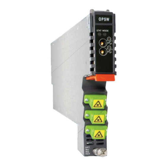
Product User Manual AIMA-OPSW 4 Module Characteristics 4.1 Module Appearance and Port Layout 4.1.1 Overview Front Panel Rear Panel Figure 4.1 Module Appearance Aug/2017 - V1 Technetix Group Limited... -
Page 11: Front Panel Layout
Product User Manual AIMA-OPSW 4.1.2 Front Panel Layout Figure 4-2 OPSW Front Panel Layout Aug/2017 - V1 Technetix Group Limited... - Page 12 OPT IN A Optical input A OPT IN B Optical input B OPT OUT Optical output Mounting Screw Fasten OPSW Module WARNING! "OPT OUT" emits a non-visible laser radiation when working. Aug/2017 - V1 Technetix Group Limited...
-
Page 13: Rear Panel Layout
Item Number Item Description Air vent Module air vent allowing air to flow out of the module Multi-pin connector Power supply and communication port Locating pin Used to position the module in the chassis Aug/2017 - V1 Technetix Group Limited... -
Page 14: Technical Description
OPT OUT Optical Output RF TP A RF A test port RF TP B RF B test port Detect A/B Amplifier Amplifier Adjustable attenuator RF Detector Detect RF TO BACK PLANE AND COMMS Data Bus Aug/2017 - V1 Technetix Group Limited... -
Page 15: Technical Overview
There is no effect on the RF testing ports regardless of whether the optical output switch is connected to InputA or InputB. RF input level measurement would work only when the optical input carrying the RF signal is within the “High Optical Input Level”. Aug/2017 - V1 Technetix Group Limited... -
Page 16: Installation
Before installing this device, you must ensure that the unit is intact and ready for installation. Unpack and check the unit: Open the box to check for any damage that may have occurred during shipment. If damage is found, please contact a Technetix customer support representative. Necessary equipment and tools for installation:... -
Page 17: Module Installation
When inserting the module into the guide rails, vertically tilt the module slightly to check that the guides are properly seated on the rails. The module is guided to the correct position using the large metal fastening screw on the lower part of the front panel. Aug/2017 - V1 Technetix Group Limited... -
Page 18: Connect The Optical Cables
To access the sliding fi bre guide you will need to fi rst remove the rear panel located on the back of the chassis. Unscrew the two thumbscrews on the rear panel. Aug/2017 - V1 Technetix Group Limited... - Page 19 Product User Manual AIMA-OPSW Then, pull the panel forward. Then lift up the handle and slide the fi bre guide out of the front of the chassis. Aug/2017 - V1 Technetix Group Limited...
-
Page 20: Using The Fiber Tray
When organising the optical fi bres, lift up the metal fl ap at the rear of the panel above the sliding guide. This will allow fi bre cables to be moved away from the sliding guide rails. Aug/2017 - V1 Technetix Group Limited... - Page 21 Product User Manual AIMA-OPSW Use the Fibre Guide Tool to organise the cables and wires in the fi bre tray to prevent tangles and the blocking of the guide rails. Fibre Tray Area Cut-outs Aug/2017 - V1 Technetix Group Limited...
-
Page 22: Cleaning The Fiber Connector Ends And The Front-Panel Optical Ports
You may need to remove excess solvent using a dry lint-free swab. Alternatively, a cleaning pen such as the one click cleaner can be used. SC one click cleaning pen www.oneclickcleaner.com Aug/2017 - V1 Technetix Group Limited... -
Page 23: Connecting The Optical Fibers
FT5X optical transmitter module. WARNING! Module emits an invisible laser when working. Avoid direct contact with the laser connector. DO NOT look directly at the fibre connector. Aug/2017 - V1 Technetix Group Limited... -
Page 24: Module Configuration & Alarms
Use a web browser to open the AIMA3000 web configuration interface at the default IP address of 192.168.25.168. Enter the default Username (admin) and Password (Technetix) to log in to the AIMA3000 system configuration web interface. Default user name: admin Default password: Technetix If you manually change the ASMM's IP address and forget it, you can still connect to the "Backup IP"... -
Page 25: Configuration Using A Android Device
“tethered” will appear on the screen and stay in the notification bar. Install the app for the Android device: If you do not have the application, contact a Technetix representative for the download information. 2. Then go back to settings. - Page 26 Lenovo Ideapad running A1_07 on Android 2.3.4. The default IP of ASMM is by Technetix for the Lenovo Ideapad running A1_07 on Android 2.3.4. The default 192.168.42.1 because the default IP of Lenovo Ideapad running in USB host mode is IP of ASMM is 192.168.42.1 because the default IP of Lenovo Ideapad running in...
-
Page 27: Restore Factory Defaults
All the powers displayed on the webpage are total power. 1 Click the module to be configured. 2 Click Apply to load factory default settings. Figure 6-1 Figure 6-1 Pacific Broadband Networks 18 January 2017 Page 29 of 49 Aug/2017 - V1 Technetix Group Limited... - Page 28 ON / OFF Retention Switch Mode Automatic / Manual Automatic Retention Revert Enable ON / OFF Retention Switch Control Path A / Path B Path A Retention Wait to Restore Time 1-10 s 10 s Retention Aug/2017 - V1 Technetix Group Limited...
-
Page 29: Reboot
The configuration of the module will not be lost after rebooting. 1 Click the module to be configured. 2 Click Apply to reboot device. Figure 6-2 Figure 6-2 Pacific Broadband Networks 18 January 2017 Page 31 of 49 Aug/2017 - V1 Technetix Group Limited... -
Page 30: Port Configuration
Product User Manual AIMA-OPSW AIMA-OPSW Product User Manual 6.4 Port Configuration 6.2 Port Configuration We recommend the operator learn the module LEDs status meanings, configuration ports, and how We recommend the operator learn the module LEDs status meanings, configuration ports, and how the module works prior to installation. - Page 31 The port page is shown in Figure 6-4 below where operator can view Port Information. Please refer to Table 6-3 for a more detailed description. Figure 6-4 Figure 6-4 Pacific Broadband Networks 18 January 2017 Page 33 of 49 Aug/2017 - V1 Technetix Group Limited...
- Page 32 Low: - 10 dBm ~ + 5 dBm (0.1 mW ~ 3.16 mW) Critical High Warning High Alarm Settings Warning Low Alarm level setting, Note: alarm parameters are allowed to be changed Critical Low Dead Band Aug/2017 - V1 Technetix Group Limited...
-
Page 33: Revert Function
InputA from InputB. The setup screen is shown in Figure 6-5. Figure 6-5 Figure 6-5 Pacific Broadband Networks 18 January 2017 Page 35 of 49 Aug/2017 - V1 Technetix Group Limited... -
Page 34: Alarm Status
Product User Manual AIMA-OPSW 6.5 Alarms Monitoring AIMA-OPSW Product User Manual All alarm information is monitored by the ASMM module. If an alarm occurs, the operator can view the associated pages to find more detailed alarm information. 6.5 Alarms Monitoring 6.5.1 Alarm Status Pages... -
Page 35: Module Operating Voltage And Temperature Alarm
Use the status indicators to determine if the module is working properly. If the device is replaced or reset, click on reset, click on Refresh to immediately poll the alarm information. "Refresh" to immediately poll the alarm information. Pacific Broadband Networks 18 January 2017 Page 37 of 49 Aug/2017 - V1 Technetix Group Limited... -
Page 36: Module Port Alarms
Product User Manual AIMA-OPSW AIMA-OPSW Product User Manual 6.5.3 Module Port Alarms 6.5.3 Module Port Alarms Click on Module Port, as shown in Figure 6-8, here the operator can view the Input Total Power and RF Output Power. Click on Module Port, as shown in Figure 6-8, here the operator can view the Input Total Power and Status has three conditions: RF Output Power. -
Page 37: Alarm Monitoring Configuration
-5.0 (ºC) +12V Input 13.5 12.0 10.5 Voltage (V) +12V Input 13.5 12.0 10.5 Voltage (V) +5V Input Voltage (V) +5V Input Voltage (V) Pacific Broadband Networks 18 January 2017 Page 39 of 49 Aug/2017 - V1 Technetix Group Limited... -
Page 38: Input / Output Status Monitoring
Product User Manual AIMA-OPSW Product User Manual AIMA-OPSW 6.6 Input / Output Status Monitoring 6.6 Input / Output Status Monitoring To setup Input / Output Status Monitoring, select the specific Port from the menu left on the left column, and the monitoring parameters are listed under Alarm Settings, check the boxes (□ √ ) to toggle To setup Input / Output Status Monitoring, select the specific Port from the menu left on the left column, and the monitoring parameters are listed under Alarm Settings, check the boxes (☑) to toggle alarms. - Page 39 Path A Optical Input 25.0 24.0 11.0 10.0 Power(dBm) Path A RF Input Level 55.9 53.9 23.9 21.9 (dBμV) Path B Optical Input 25.0 24.0 11.0 10.0 Power(dBm) Path B RF Input 55.9 53.9 23.9 61.9 Level(dBmV) Aug/2017 - V1 Technetix Group Limited...
-
Page 40: Logs Management
Product User Manual AIMA-OPSW Table 6-6 Module Alarm Indicator Definitions AIMA-OPSW Product User Manual Parameters (Common) Description Definitions Related Indicators Lighting Conditions Table 6-6 Module Alarm Indicator Definitions Power OFF Power OFF Power OFF All OFF Initiating Application During Module... -
Page 41: Device Upgrade
PBN’s NMSE management software. Please refer to the NMSE Product User Manual for more information. * The OPSW supports automated fi rmware updates and automatic backup & restore features via TFTP when managed by Technetix NMSE management software. Please refer to the NMSE Product User Manual for more information. -
Page 42: Troubleshooting
Input A/B signal is too high or too low. Adjust input signal to an appropriate value. The RF output power is too high or too low. Please contact Technetix's technical support STAT red Power Failure Please contact Technetix's technical support Lower the room temperature. -
Page 43: Product Warranty
The warranty registration has been completed and received by Technetix. 2. Technetix's helpdesk is promptly notified in writing or by telephone, by sending an e-mail to (INSERT EMAIL ADDRESS) that a failure or defect has occurred. 3. A return authorization number is obtained from Technetix's helpdesk and clearly marked on the outside of the shipping container and all documents. -
Page 44: Declaration Of Conformity
9 Declaration of Conformity According to ISO/IEC Guide 22 and EN45014 Manufacturer's Name: Technetix Manufacturer’s Address: Technetix Ltd, Innovation House, Technetix Business Park, Albourne, West Sussex, BN6 9EB Product Name: OPSW – Optical A/B Protection Switch Conforms to the following standards:... -
Page 45: Appendix A: Default Alarm Limit Settings
Appendix A: Default Alarm Limit Settings Critical Warning Warning Critical Dead Factory Parameter Normal High High Band Default Temperature (°C) 70.0 65.0 28.0 -5.0 +5V Input voltage (V) +12V Input voltage (V) 13.2 12.0 10.8 Aug/2017 - V1 Technetix Group Limited... -
Page 46: Appendix B: Db Conversion Table
Product User Manual AIMA-OPSW Appendix B: dB Conversion Table dBmV dBμV dBmV dBμV Aug/2017 - V1 Technetix Group Limited...