
Related Manuals for technetix AIMA-RFSW


Summary of Contents for technetix AIMA-RFSW
- Page 1 AIMA-RFSW RF A/B PROTECTION SWITCH Product user manual Online Email: customer.service.vdl@technetix.com Website: technetix.com Technetix Group Limited 2018-08/EN V1...
-
Page 2: Table Of Contents
5.4 Check module LEDs ....................................11 5.5 Test the RF input signal....................................11 Module configuration & alarm setup ........................12 6.1 Port configuration screen ..................................12 6.2 Restoring factory default ..................................14 6.3 Reboot ...........................................15 6.4 Alarms monitoring......................................17 6.4.1 Alarm status pages....................................17 2018-08/EN V1 Technetix Group Limited... - Page 3 6.5.1 Monitoring function ON/OFF ................................20 6.5.2 Temperature, +12V/+5V voltage alarm level management ......................21 6.5.3 Input/Output status monitoring ................................22 6.6 Logs management ....................................24 6.7 Device uprade ......................................25 Troubleshooting .................................26 Appendix A: Default alarm limit settings ........................27 2018-08/EN V1 Technetix Group Limited...
-
Page 4: About This Manual
NMS3-EPSM - Basic System Management • NMS3-EPSM - Basic Template Management 1.2 Technical Support If you need help in the process of setting up and maintaining RFSW, please contact Technetix customer service: Europe: Technetix BV Kazemat 5 NL-3905 NR Veenendaal P.O. -
Page 5: Precautions
Outage or overload requiring service and repairs Unplug the unit and refer the servicing to Technetix qualified service personnel only. Servicing and repairs DO NOT attempt to service this unit yourself. Refer all servicing needs to Technetix qualified service personnel only. 2018-08/EN V1... -
Page 6: Overview
Remote firmware upgrade and auto upload/download of configuration files through ASMM webinterface or using the NMSE ■ Bulk firmware updates through the NMSE ■ FCC, CE and RCM compliant See Declaration of Conformity for current status. 2018-08/EN V1 Technetix Group Limited... -
Page 7: Specifications
Maximum 90 % (Non-condensing) Storage temperature -25 - 70°C Storage humidity 90% (non-condensing) Dimensions (W*D*H) 24.6 * 410 * 152.5 mm Weight 0.88 kg Supported network management options The NMSE or through ASMM’s Web Interface 2018-08/EN V1 Technetix Group Limited... -
Page 8: Block Diagram
Product user manual AIMA-RFSW 3.3.1 Block Diagram Figure 3-1 RFSW block diagram 3.4 Order Details A-RFSW-[Z] RF A/B protection switch Options: Bandwidth 45 - 1000 MHz (Standard) 5 - 1218MHz 2018-08/EN V1 Technetix Group Limited... -
Page 9: Module Characteristics
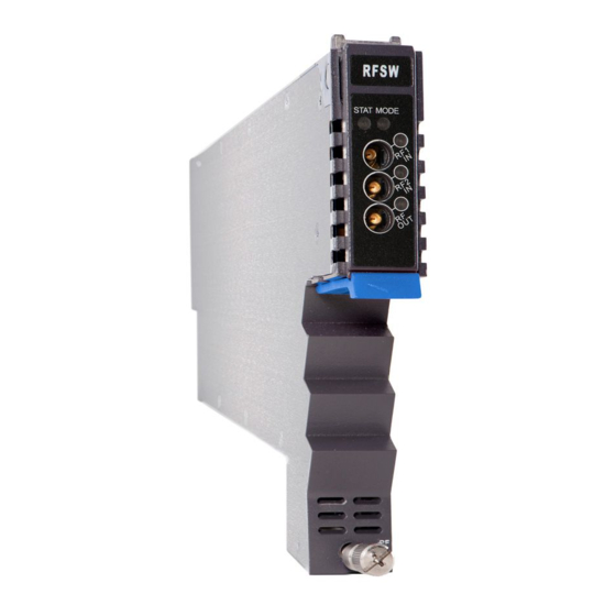
Product user manual AIMA-RFSW 4 Module Characteristics 4.1 Module Appearance and Port Layout 4.1.1 Overview Figure 4-1 Module appearance 2018-08/EN V1 Technetix Group Limited... -
Page 10: Front Panel Layout
RF working mode indicator Normal: Green Major Alarm: Red Minor Alarm: Orange RF OUT TP RF output testing point Plug and fix the module. The tab-retaining clip will pop-up after pressing the Tab-retaining clip release and plug module. Front screw Fix RFSW Module 2018-08/EN V1 Technetix Group Limited... -
Page 11: Rear Panel Layout
RF input B RF out RF output Air vent Air vent allowing air to flow out of the module Multi-pin connector Power and communcation port Placement Pin Used to position the module in the chassis 2018-08/EN V1 Technetix Group Limited... -
Page 12: Installation
Before installing this device, you must ensure that the unit is intact and ready for installation. Unpack and check the unit: Open the box to check for any damage that may have occurred during shipment. If damage is found, please contact a Technetix customer support representative. Necessary equipment and tools for installation:... -
Page 13: Module Installation
Pacific Broadband Networks 15 January 2015 Page 16 of 36 2018-08/EN V1 Technetix Group Limited... -
Page 14: Check Module Leds
RF test point readings. When testing the RF signal at TP port, make sure that the RF output port is either connected with an RF load or has 75 Ω terminator installed. 2018-08/EN V1 Technetix Group Limited... -
Page 15: Module Configuration & Alarm Setup
'RFSW' from the left column to configure the RFSW. After selecting the 'RFSW', the main RFSW settings page will appear to configure the module parameters. On the main window in the 'Alarm Setting' section, various alarms can be toggled. 2018-08/EN V1 Technetix Group Limited... - Page 16 Input limits can be set by configuring the parameters for the 'Critical Alarm' and 'Low Alarm'. When a 'Critical High' or 'Critical Low' Alarm occurs, the RFSW will automatically switch to 'Path A' (when no critical high or low alarms exist on 'Path A'). 2018-08/EN V1 Technetix Group Limited...
-
Page 17: Restoring Factory Default
Table 6-1. Note: All the powers displayed on the webpage are total power. 1 Click the module to be configured 2 Click 'Apply' to load factory default settings Figure 6-1 2018-08/EN V1 Technetix Group Limited... -
Page 18: Reboot
'Apply' button next to the Reboot label. Next, click 'Submit' to confirm, and the module will automatically restart. The module's configuration will not be lost after rebooting. 1 Click the module to be configured 2 Click 'Apply' to reboot device Figure 6-2 2018-08/EN V1 Technetix Group Limited... - Page 19 FW Part No Firmware package number Configuration Alarm Control Control Alarm Indicator ON/OFF Enable/Disable Critical High Warning High Alarm level setting, alarm parameters Alarm Setting Warning Low are not allowed to be changed Critical Low Deadband 2018-08/EN V1 Technetix Group Limited...
-
Page 20: Alarms Monitoring
Click the 'Alarms' tab on the top menu bar to display an overview of the alarm status of all the installed modules as shown in Figure 6-3 below. There are three alarm statuses: ■ Normal: Green light ■ Major alarm: Orange light ■ Major alarm: Red light Figure 6-3 2018-08/EN V1 Technetix Group Limited... -
Page 21: Module Operating Voltage And Temperature Alarm
Major alarm: Orange light ■ Major alarm: Red light Figure 6-4 Use the status indicators to determine if the module is working properly. If the device is replaced or reset, click 'Refresh' to update the alarm information. 2018-08/EN V1 Technetix Group Limited... -
Page 22: Module Port Alarms
Click on 'Port' under the associated RFSW from the left column, as shown in Figure 6-5. From the 'Port' screen, the operator can view the Input Total Power, and the Input Level alarms status. There are three alarm statuses: ■ Normal: Green light ■ Major alarm: Orange light ■ Major alarm: Red light Figure 6-5 2018-08/EN V1 Technetix Group Limited... -
Page 23: Alarm Monitoring Configuration
Product user manual AIMA-RFSW 6.5 Alarm monitoring configuration 6.5.1 Monitoring Function ON / OFF The Monitoring Function is labeled as 'Alarm Control' and it can be toggled from the 'Configuration' section on the 'Modules' page. 2018-08/EN V1 Technetix Group Limited... -
Page 24: Temperature, +12V/+5V Voltage Alarm Level Management
Critical Warning Warning Critical Dead Factory Parameters Normal High High Band Default Temperature (°C) 70.0 65.0 -5.0 Temperature +5V Input Voltage (V) Input Voltage +12V Input Voltage 13.5 12.0 10.5 (V) Input Voltage Figure 6-6 2018-08/EN V1 Technetix Group Limited... -
Page 25: Input/Output Status Monitoring
Normal High High Band Default Path A Input 70.8 66.8 48.8 44.8 -58.0 Level (dBmV) Path B Input 70.8 66.8 48.8 44.8 -58.0 Level (dBmV) Output Power 68.8 64.8 46.8 42.8 -58.0 (dBmV) Figure 6-7 2018-08/EN V1 Technetix Group Limited... - Page 26 RF Output Power RF Output Power is RF-output-Critical-ALM STAT RF OUT Critical Alarm too high or too low RF Output Power RF Output Power is RF-output-Minor-ALM STAT RF OUT Orange Warning Alarm higher or lower 2018-08/EN V1 Technetix Group Limited...
-
Page 27: Logs Management
The operator can view all the alarms of the modules in the chassis on the 'Logs Management' page. Click 'Logs' on the top menu bar to enter the 'Logs Management' page. See Figure 6-8 below: Figure 6-8 2018-08/EN V1 Technetix Group Limited... -
Page 28: Device Uprade
Module will be upgraded after the firmware is uploaded. The upgrading and reboot process will take about 30 seconds. During the upgrading, please don’t power off the device and don’t plug any module in the same chassis, or it may lead to upgrade fail or data sync error. 2018-08/EN V1 Technetix Group Limited... -
Page 29: Troubleshooting
Channel A/B Input level is too Adjust channel A/B input signal high or too low Power failure Please contact Technetix technical support STAT is Red RF output level is too high or too low Adjust channel A/B input signal Lower the room temperature if the... -
Page 30: Appendix A: Default Alarm Limit Settings
AIMA-RFSW Appendix A: Default alarm limit settings Critical Warning Warning Critical Dead Factory Parameters Normal High High Band Default Temperature 70.0 65.0 -5.0 (°C) +5V Input Voltage (V) +12V Input 13.5 12.0 10.5 Voltage (V) 2018-08/EN V1 Technetix Group Limited...
Need help?
Do you have a question about the AIMA-RFSW and is the answer not in the manual?
Questions and answers