Table of Contents

Related Manuals for ZIROX SGM7.2.4


Summary of Contents for ZIROX SGM7.2.4
- Page 1 ZIROX - Oxygen Measuring Systems SGM7.2.4 SGM7.2.6 Oxygen Measuring Device Reflow Soldering Systems ZIROX Sensoren & Elektronik GmbH Am Koppelberg 21, 17489 Greifswald, Germany +49 3834 8309 -00, Fax: -29 E-mail: info@zirox.de...
- Page 3 SGM7.2.4 SGM7.2.6 Manual Oxygen Measuring Device Reflow Soldering Systems Range: 2 · 10 ... 10 vol-ppm Power supply: 100…240 V, 47…63 Hz Operating hour counter Indication of maintenance interval for filter change (depends on pump mode)
-
Page 4: Table Of Contents
5.3.1 General data ................ 13 Interface data .................. 14 5.4.1 Pump control ................ 15 Composition of the oxygen monitor SGM7.2.4 ........16 General composition ................ 16 6.1.1 General overview ..............16 6.1.2 Construction principle of the solid electrolyte sensor .... 17 6.1.3 Electronic data processing ........... - Page 5 Oxygen Monitor SGM7.2.4/7.2.6 Content 8.2.1 Adjustable parameters ............25 8.2.2 Programming menus ............26 Calibration ..................29 8.3.1 Zero calibration ..............29 8.3.2 Span gas calibration ............. 29 8.3.3 Calibration status ..............30 Fault clearance ................30 Maintenance, overhaul and storage ............31 General instructions .................
-
Page 6: General Information
SGM7.2.4 with the aim of making technical improvements, the user is responsible for inserting the additional or updated pages supplied. Proper operation of the SGM7.2.4 can only be ensured if the contents of this manual are known. Therefore, all chapters of this manual must be read carefully prior to operating the SGM7.2.4. -
Page 7: Commonly Used Symbols
Oxygen Monitor SGM7.2.4/7.2.6 1 General information Commonly used symbols Symbol for imminent danger: This symbol refers to imminent danger to persons’ life and health. danger In case of disregard, fatal injuries may result. Symbol for indirect danger: This symbol indicates indirect danger. -
Page 8: Application Field
• production processes of electronic components under buffer gas. The introduction of explosive gas compounds, high concentrations of halogens or sulphuric gases (e.g. SO ) into the SGM7.2.4 is not permitted. The contact of the SGM7.2.4 with siliconic or phosphoric compounds is not permitted either. Functions The SGM7.2.4 •... -
Page 9: Safety Regulations
3 Safety regulations 3 Safety regulations The following regulations for industrial safety provide basic information about potential danger during the operation of the buffer gas monitor SGM7.2.4. Therefore, they must be observed and strictly followed by the responsible staff. • A failure-free and functional operating of the SGM can only be guaranteed with knowledge of this manual. -
Page 10: Functional Description
O2, meas.gas in the measuring gas in Pa. The sensor of the SGM7.2.4 is based on the conductivity of oxide ions in a special ceramic substance (zirconium dioxide) with stabilizing additions. The conductivity of these oxide ions increases exponentially with the temperature and reaches a sufficiently high temperature above 600°C. -
Page 11: General Recommendation
Oxygen Monitor SGM7.2.4/7.2.6 4 Functional description Based on the assumption that the total pressures of the gases are almost Equation for oxygen the same at both electrodes (in this case the volume concentrations may concentr. be used in the calculation instead of the partial pressures) and replacing the parameters by numbers in equation (I) the following equation applies: (-46,42 ·... -
Page 12: Accuracy Of The Measurement
• The measuring gas must be extracted where a formation of layers can be avoided. • The tube from the measuring point to the SGM7.2.4 must be as short as possible in order to avoid a change in the chemical balance in the tube. -
Page 13: Technical Data
Oxygen Monitor SGM7.2.4/7.2.6 5 Technical data Technical data Characteristics Description..........Protective gas monitor SGM7.2.4 Application ..........Measuring of the oxygen concentration in inert gases Measuring range ........10 vol-ppm…20.6 vol% O Accuracy at normal pressure ....Relative measuring error < 5 % Measuring gas flow rate ...... -
Page 14: Interface Data
Operation hour meter run out! Change filter or carbon, then reset! (see manual) ERROR6 System error Analog output SGM7.2.4: Voltage output, 0/2 - 10V, potential-free, range adjustable SGM7.2.6: Current output, 0/4 – 20 mA, potential-free, range adjustable Chart 3: Limit value relay Charge Resistive charge (cosϕ... -
Page 15: Pump Control
Oxygen Monitor SGM7.2.4/7.2.6 5 Technical Data 5.4.1 Pump control A powerful pump is integrated in the SGM7.2.4, which can be controlled via interface RS232: Chart 4: pump control via RS232 Command from Reply of SGM7.2.4 Remark P0CR P0CR pump off... -
Page 16: Composition Of The Oxygen Monitor Sgm7.2.4
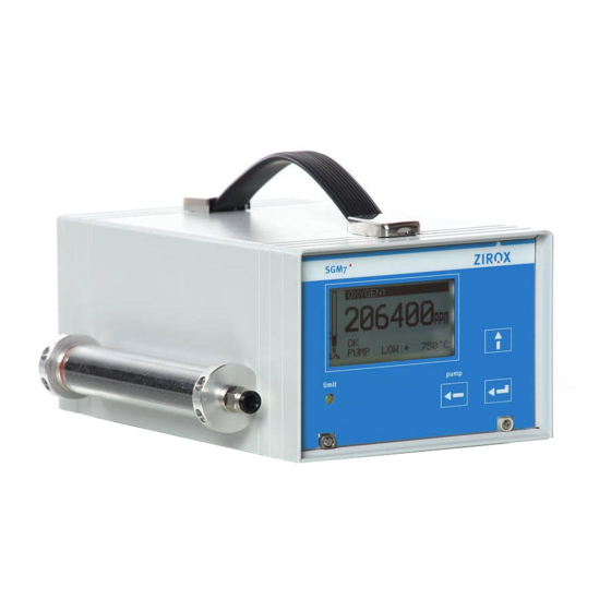
6 Composition of the oxygen monitor SGM7.2.4 General composition 6.1.1 General overview The SGM7.2.4 is a portable device. The general composition is shown in Fig. 1. Fig. 1: General composition of the SGM7.2.4 The measuring gas gets into the sensor by means of little overpressure at the inlet or the optional pump ingests the measuring gas. -
Page 17: Construction Principle Of The Solid Electrolyte Sensor
A thermocouple (2/5) inside the measuring cell determines the actual electrode temperature. A regulator ensures a constant temperature. The heated measuring cell produces thermal energy. Therefore, the SGM7.2.4 must not be covered. -
Page 18: Electronic Data Processing
The following block diagram illustrates the data processing. Sensor Sensor Surveillance Amplifier for Amplifier for Thermocouple Cell Voltage Display Keyboard Heater Microcontroller Control DC-Output Relay Outputs RS-232 0.8 A Analog out Pow er Supply 1.0 A 110-230 V/50-60 Hz Fig. 3: Block diagram of the SGM7.2.4... -
Page 19: Usage And Connection Elements
Oxygen Monitor SGM7.2.4/7.2.6 6 Composition Usage and connection elements 6.2.1 Current supply The SGM7.2.4 is firmly connected to the current supply by a connecting cable. 6.2.2 Front The indicators and control elements are located on the front of the SGM7.2.4. Depending on the size, the measuring values are displayed either in vol% or in vol-ppm. -
Page 20: Rear
The gas inlet is connected with the carbon filter. The inlet of the filter is located on the front side. The line cord is permanently fixed with the device. It cannot be connected. Fig. 5: Rear of the SGM7.2.4... -
Page 21: Installation And Initiation
A waiting time of about 2 hours before switching-on must be considered. 1. Install the SGM7.2.4 in the favored place (see chapter 7.1). 2. Connect point of measurement and places of gas inlet and outlet of the SGM7.2.4. Pay attention to leak-tightness. - Page 22 Oxygen concentration of < 100 ppm ....Stainless steel tube. Silicone can cause measuring inaccuracies because of its oxygen permeability. Therefore, the manufacturer advises against a usage. NOTE The measuring gas can also flow through the SGM7.2.4 when it is off.
-
Page 23: Operation And Parametrization
After switch-on, the SGM7.2.4 is in display mode. On the display the programmed measuring value for output 1 is shown (normally the oxygen concentration) according to the chosen dimension. -
Page 24: Status And Error Messages
The relay output is activated simultaneously. Chart 6: Status / error messages Status Display Remark LIMIT RANGE <<< No alarm (only SGM7.2.4)! Several reasons – see chapter RANGE >>> FLOW <<< < 8 l/h FLOW >>> > 35 l/h Change filter! >... -
Page 25: Parametrization
Parameter Range Remarks : 0…21 vol% or in ppm Range up to 100 vol% on Display request 0-10 V or 2-10 V (SGM7.2.4) Analog output 0...20 mA or 4...20 mA (SGM7.2.6) Logarithmic scale Linear recommended if Scale of output measuring value exceeds Logarithmic (Basis 10) several decades. -
Page 26: Programming Menus
Oxygen Monitor SGM7.2.4/7.2.6 8 Operation 8.2.2 Programming menus The keys below the display refer to the following menus (the current meaning of the respective key is shown on the display). A definite parameter can be chosen, changed and finally confirmed with the -key. - Page 27 DELAY TIME: 1sec 0...99sec RETURN B.4 Output ANALOG OUTPUT VALUE: ppm O2 vol% O2, O2[log10] RANGE: 0-10 V 2-10V(SGM7.2.4), 0-20 or 4-20 mA (SGM7.2.6) ZERO POINT: 0 ppm END MARK: 210000 ppm AVERAGE FACTOR: 1sec 1-99sec RETURN B.5 Calibration CALIBRATION CALIBR.
- Page 28 Oxygen Monitor SGM7.2.4/7.2.6 8 Operation B.5.1 Calibration zero point CALIBR. ZERO POINT MEAS. VALUE: 206400 ppm Current measuring value ZERO GAS: 206400 ppm ZERO GAS always 20.64 % (surrounding air) CALIBR: ZERO: WAIT 5 Status CALIBR. VALUE: - 4.5 Calibration value RETURN *1 If this line is activated and key Enter is pressed for approx.
-
Page 29: Calibration
Oxygen Monitor SGM7.2.4/7.2.6 8 Operation Calibration For measurements with high accuracy requirements a calibration is highly recommended (The high stability of the measuring cell requires one check-up per a year only!). The device must be in operating state for a minimum of one hour before the calibration! 8.3.1 Zero calibration... -
Page 30: Calibration Status
Oxygen Monitor SGM7.2.4/7.2.6 8 Operation 8.3.3 Calibration status Chart 8: Messages calibration status OK (1.5) last calibration OK (calibration value) WAIT ! calibration is running BREAK cancelled by pressing key TIME OUT stability not reached within 60sec OUT OF RANGE... -
Page 31: Maintenance, Overhaul And Storage
Oxygen Monitor SGM7.2.4/7.2.6 9 Maintanance and Storage 9 Maintenance, overhaul and storage General instructions The electronics and the measuring cell are maintenance-free. In case of defects in measuring cell or thermocouple, send the SGM to the manufacturer for an overhaul. -
Page 32: Appendix
Oxygen Monitor SGM7.2.4/7.2.6 10 Appendix 10 Appendix 10.1 Activated carbon filter: description and application notes 10.1.1 Filter construction The figure above shows the carbon filter. Two caps with tube connections close the acryl glass container containing the activated carbon. Both caps are inserted into the tube (sealed by O-seal). -
Page 33: Replacement Of Activated Carbon
Oxygen Monitor SGM7.2.4/7.2.6 10 Appendix 10.1.3 Replacement of activated carbon Please follow the instructions for replacing the activated carbon. 1) Separate gas connections of the filter at gas inlet and outlet 2) Loosen all four M3-screws which connect filter and housing... -
Page 34: Technical Data
Oxygen Monitor SGM7.2.4/7.2.6 10 Appendix 10.1.4 Technical data Weight Approx. 120 g Volume Approx. 100 ml Duration of operation Depending on the components and the concentration of the adsorbed organic components e.g. approx. 1…3 months at raw gas from a fermenting... -
Page 35: Eu Declaration Of Conformity
Oxygen Monitor SGM7.2.4/7.2.6 10 Appendix 10.2 EU Declaration of conformity... -
Page 36: Warranty Conditions
In case of defects and faults within 12 months (probe) and 24 months (electronics assembly) respectively after dispatch, ZIROX will clear faults at its own option by repair or replacement. The purchaser must give prompt written notice to ZIROX. -
Page 37: Your Own Notes And Remarks
Oxygen Monitor SGM7.2.4/7.2.6 11 Your notes 11 Your own notes and remarks...
Need help?
Do you have a question about the SGM7.2.4 and is the answer not in the manual?
Questions and answers