Table of Contents
Advertisement
General Warranty
OWON warrants that the product will be free from defects in materials and workmanship for a period
of 3 years (1 year for accessories) from the date of purchase of the product by the original purchaser
from the OWON Company. This warranty only applies to the original purchaser and is not transferable
to the third party.
If the product proves defective during the warranty period, OWON either will repair the defective
product without charge for parts and labor, or will provide a replacement in exchange for the defective
product. Parts, modules and replacement products used by OWON for warranty work may be new or
reconditioned like new performance. All replaced parts, modules and products become the property of
OWON.
In order to obtain service under this warranty, customer must notify OWON of the defect before the
expiration of the warranty period. Customer shall be responsible for packaging and shipping the
defective product to the service center designated by OWON, and with a copy of customer proof of
purchase.
This warranty shall not apply to any defect, failure or damage caused by improper use or improper or
inadequate maintenance and care. OWON shall not be obligated to furnish service under this warranty
a) to repair damage resulting from attempts by personnel other than OWON representatives to install,
repair or service the product; b) to repair damage resulting from improper use or connection to
incompatible equipment; c) to repair any damage or malfunction caused by the use of non-OWON
supplies; or d) to service a product that has been modified or integrated with other products when the
effect of such modification or integration increases the time or difficulty of servicing the product.
Please contact the nearest OWON's Sales and Service Offices for services.
For better after-sales service, please visit
www.owon.com.cn
and register the purchased product online.
Excepting the after-sales services provided in this summary or the applicable warranty
statements, OWON will not offer any guarantee for maintenance definitely declared or hinted,
including but not limited to the implied guarantee for marketability and special-purpose
acceptability. OWON should not take any responsibilities for any indirect, special or consequent
damages.
For more details, please refer to the user manual on the supplied CD, it can also be downloaded at
www.owon.com.cn
.
Advertisement
Table of Contents

Related Manuals for Owon XDG2000 Series


Summary of Contents for Owon XDG2000 Series
- Page 1 General Warranty OWON warrants that the product will be free from defects in materials and workmanship for a period of 3 years (1 year for accessories) from the date of purchase of the product by the original purchaser from the OWON Company. This warranty only applies to the original purchaser and is not transferable to the third party.
-
Page 2: Table Of Contents
Table of Contents 1.General Safety Requirement ..............1 2.Safety Terms and Symbols ..............2 3.General Inspection ................3 4.Quick Start .................... 4 Front panel overview ........................4 Rear Panel Overview ........................6 Power on ............................. 7 User Interface ..........................8 Use build-in Help ......................... -
Page 3: General Safety Requirement
1.General Safety Requirement 1. General Safety Requirement Before any operations, please read the following safety precautions to avoid any possible bodily injury and prevent this product or any other products connected from damage. In order to avoid any contingent danger, this product is only used within the range specified. Use Proper Power Cord. -
Page 4: Safety Terms And Symbols
2.Safety Terms and Symbols 2. Safety Terms and Symbols Terms in this Manual. The following terms may appear in this manual: Warning: Warning indicates the conditions or practices that could result in injury or loss of life. Caution: Caution indicates the conditions or practices that could result in damage to this product or other property. -
Page 5: General Inspection
Enclosure of this Manual. You can check whether there is any loss of accessories with reference to this description. If it is found that there is any accessory lost or damaged, please get in touch with the distributor of OWON responsible for this service or the OWON's local offices. -
Page 6: Quick Start
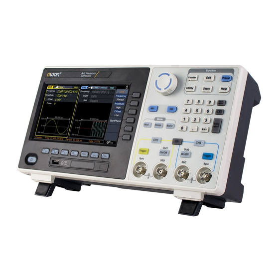
4.Quick Start 4. Quick Start Front panel overview Figure 4-1 Front Panel overview Display the user interface Menu Includes 6 keys to activate the corresponding menu selection keys Mode keys Mod:output the modulated waveform Sweep: scan the sine, square,ramp or arbitrary waveforms Burst:generate the sine, square, ramp, pulse or arbitrary burst Knob... - Page 7 4.Quick Start Operation Counter:enter the counter interface keys Edit:enter the wavform edit interface Preset:enter the preset menu, set the reset parameter or power-on parameter; save or load the setting file. Utility:set the utility function Store:save/load arbitrary waveform or instrument setup Help:To get contextual help for any front panel button or menu softkey, press the button and then press the button for which you need help.
-
Page 8: Rear Panel Overview
4.Quick Start Yellow Trigger button:CH1 manual trigger button. In sweep or burst mode, when the trigger source is selected as “Manual”, each press of this button will initiate a trigger. On/Off button:Turns the output of the CH1 channel on or off. -
Page 9: Power On
4.Quick Start 2 Air vents 3 AC input connector AC input connector 4 Fuse Container The place to install the fuse 5 Foot Stool Tilt the signal generator for easy operation. 6 COM interface This interface can be used to connect with PC. (optional) 7 LAN interface The network port which can be used to connect... -
Page 10: User Interface
4.Quick Start Warning: To prevent electric shock, make sure the instrument is properly grounded. (2) Press the power button on the front panel. The startup screen will display. User Interface Figure 4-3 User Interface 1 Display channel name and channel switch status 2 Current waveform or current mode 3 Trigger source Internal:Internal modulation or internal trigger source... -
Page 11: Use Build-In Help
4.Quick Start 8 Current menu name 9 Current waveform or mode setting menu 10 Counter brief information showing frequency value, period value 11 Display current waveform 12 Start phase 13 Offset / low level, depending on the right highlighted menu item 14 Amplitude / high level, depending on the right highlighted menu Frequency/cycle, depending on the highlighted menu item on the right... - Page 12 4.Quick Start interface. The waveform is different and the parameters that can be set are different. Example: Press the key and press the Frequency/Period soft key. The selected menu item is highlighted on white, and the cursor will display on corresponding parameter item...
-
Page 13: Output The Build-In Waveform (Including Dc)
4.Quick Start Width/DutyCyc, Rising/Falling Noise Amplitude/High, Offset/Low Arbitrary Frequency/Period, Amplitude/High, Offset/Low, StartPhase, Bult-in Frequency/Period, Amplitude/High, Offset/Low, StartPhase, Type, Harmonic Order, SN, Amplitude, Phase Output the build-in waveform (including DC) (1) Press the arbitrary wave button to enter the arbitrary wave menu and configure the waveform parameters. -
Page 14: Generate The Modulated Waveform
4.Quick Start means the file is empty.) Description: EditMemory is a temporary data space created, saved, edited or recalled by any arbitrary wave. Saving the waveform is to save the data of this space to the user-specified location (EditMemory is in the memory and never empty). The data in this space is changed after an arbitrary waveform is called, a new waveform is created, or a related programming command is received. -
Page 15: Generate Sweep
4.Quick Start Internal source Shape, FM Frequency, Deviation External source Deviation Internal source Shape, PM Frequency, Phase Deviation External source Phase Deviation Internal source Shape, PWM Frequency, Duty Deviation External source Duty Deviation Internal source ASK Rate, Amplitude External source Slope, Amplitude Internal source PSK Rate, Phase Deviation... -
Page 16: Counter
4.Quick Start be set in N-Cycle mode. Polarity is available in Gated mode. Counter The frequency counter measures signals in the frequency range from 100 mHz to 200 MHz. The [10MHz In/Out/Counter] connector on the rear panel is used by default to receive the frequency counter input signal. The frequency meter works from the start, unless the connector is set to an external clock input or clock output. -
Page 17: File Store System
4.Quick Start (4) The frequency, period, duty cycle, positive pulse width, and negative pulse width can be viewed on the frequency meter interface. If it is not currently in frequency counter interface, the frequency, period and duty cycle can be viewed in the frequency counter bar at the bottom of the screen. -
Page 18: Bring Up Arbitrary Wave Files In Internal/External Memory
4.Quick Start to enter the currently selected folder. To return to the parent directory, press the Back softkey. After selecting the storage path, press the SaveAs softkey and the input keyboard appears on the screen. Turn the knob to select a character. Press the ABC/abc softkey to toggle the case of keyboard characters. -
Page 19: Save/Recall Instrument Setup
4.Quick Start (2) Select INTER under the memory selection interface, and then press the Arb file softkey. (3) Press the Secure softkey, the screen pops up, and then press the OK softkey to erase all waveforms stored in internal memory. Save/recall instrument setup The instrument settings can be saved as files in internal memory. - Page 20 4.Quick Start CH2 Sync Enable/disable front panel CH2 sync output terminal to output sync signal CH1 Load It is convenient for the user to match the display voltage with the desired load. The range is from 1 Ω to 10 kΩ CH2 Load I/O Setting Set the communication protocol type of the USB Device interface on the rear...
-
Page 21: Communicate With Pc
5.Communicate with PC 5. Communicate with PC Supports communication with a computer via a USB port or a LAN port. Using the Waveform Editor software installed on the computer, the signal generator can be operated on the computer to control the output of the signal generator. Here's how to connect to a computer. -
Page 22: Connect Through A Router
5.Communicate with PC last field has a different IP address. It is "192.168.1.99"; the port can be set to any value from 0 to 4000. However, since ports below 2000 are often occupied, it is recommended to set it to 2000 or higher. Here, it is set to "3000". Figure 5-1: Setting the network parameters of the host computer (4) Set the network parameters of the signal generator. - Page 23 5.Communicate with PC Figure 5-1:Set the network parameters of the host computer (4) Set the network parameters of the signal generator. In the signal generator, press Utility → I/O Setup → Network setting to enter the submenu. Set the IP address and port to the IP and port in the PC software port settings in step (3).
-
Page 24: Appendix
6.Appendix 6. Appendix Appendix A:Accessories 1 × power cord that meets the standards of the country where you are located 1 × USB communication cable 1 × CD with communication software 1 × Quick Guide 2 × BNC/Q9 cable Appendix B:General Care and Cleaning General Maintenance Do not store or leave the instrument where the liquid crystal display will be exposed to direct...
Need help?
Do you have a question about the XDG2000 Series and is the answer not in the manual?
Questions and answers