Table of Contents
Advertisement
Quick Links
Advertisement
Table of Contents

Subscribe to Our Youtube Channel
Related Manuals for Owon XDG2030


Summary of Contents for Owon XDG2030
- Page 1 XDG2030 Dual-Channel Arbitrary Waveform Generator User Manual www.owon.com...
- Page 2 LILLIPUT Company. Fujian LILLIPUT Optoelectronics Technology Co., Ltd. No. 19, Heming Road Lantian Industrial Zone, Zhangzhou 363005 P.R. China Tel: +86-596-2130430 Fax: +86-596-2109272 Web: www.owon.com E-mail: info@owon.com.cn...
- Page 3 Parts, modules and replacement products used by OWON for warranty work may be new or reconditioned like new. All replaced parts, modules and products become the property of OWON.
-
Page 4: Table Of Contents
Table of Contents 1.General Safety Requirement ..............1 2.Safety Terms and Symbols ..............2 3.General Inspection ................3 4.Quick Start .................... 4 Front Panel Overview ........................ 4 Rear Panel Overview ......................... 6 Foot Stool Adjustment ......................7 Power On ........................... 7 User Interface .......................... - Page 5 Set the harmonic phase of each order ..............25 Output the Modulated Waves ....................25 AM (Amplitude Modulation) ................... 26 DSB-AM (Double-Sideband AM) ..................27 FM (Frequency Modulation) ................... 28 PM (Phase Modulation) ....................30 PWM (Pulse Width Modulation) ..................31 ASK (Amplitude Shift Keying) ..................
- Page 6 Erase waveforms from memory ..................57 Save/recall Instrument Settings ..................58 Preset Settings (Preset) ......................58 Restore to the factory setting ..................58 Restore to the user setting ....................62 Power-on setting ......................63 Use Build-in Help (Help) ......................63 6.Communicate with PC .................
-
Page 7: General Safety Requirement
1.General Safety Requirement 1. General Safety Requirement Before any operations, please read the following safety precautions to avoid any possible bodily injury and prevent this product or any other products connected from damage. In order to avoid any contingent danger, this product is only used within the range specified. -
Page 8: Safety Terms And Symbols
2.Safety Terms and Symbols 2. Safety Terms and Symbols Safety Terms Terms in this Manual. The following terms may appear in this manual: Warning: Warning indicates the conditions or practices that could result in injury or loss of life. Caution: Caution indicates the conditions or practices that could result in damage to this product or other property. -
Page 9: General Inspection
You can check whether there is any loss of accessories with reference to this description. If it is found that there is any accessory lost or damaged, please get in touch with the distributor of OWON responsible for this service or the OWON's local offices. 3. Check the Complete Instrument... -
Page 10: Quick Start
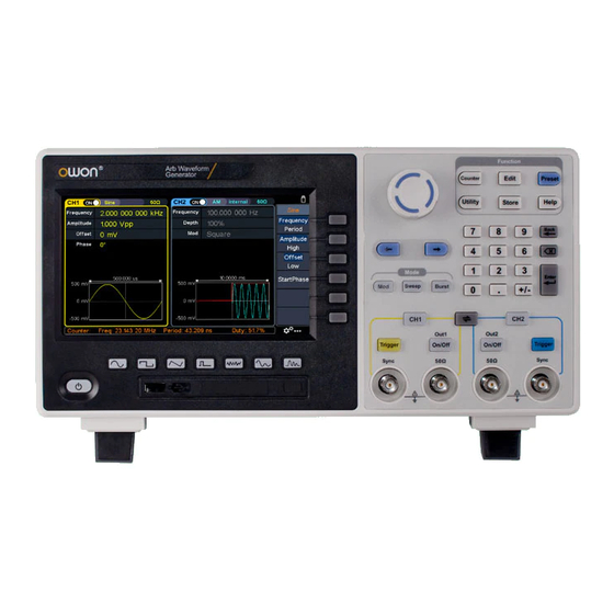
4.Quick Start 4. Quick Start Front Panel Overview Figure 4-1: Front Panel overview Display the user interface Menu selection Includes 6 keys to activate the corresponding menu keys Mode keys Mod: Output the modulated waveform Sweep: Scan the sine, square, ramp or arbitrary waveforms Burst: Generate the sine, square, ramp, pulse or arbitrary burst Change the currently selected value, also used to select the Knob... - Page 11 4.Quick Start Utility: Set the utility function Store: Save/load arbitrary waveform or instrument setup Help: To get contextual help for any front panel button or menu softkey, press the button and then press the button for which you need help. Number keypad Input the parameter CH2 button: After entering the waveform interface and CH2 Function...
-
Page 12: Rear Panel Overview
4.Quick Start 16 USB interface Connect with external USB devices, e.g. U disk. 17 Power button Turn on/off the waveform generator. Rear Panel Overview Figure 4-2: Rear Panel Overview 1 Retractable handle 2 Air vents 3 AC input connector AC input connector 4 Fuse Container The place to install the fuse 5 Foot Stool... -
Page 13: Foot Stool Adjustment
4.Quick Start 9 Lock Hole You can lock the device to a fixed location using the security lock (please buy it yourself) to secure the device. 10 10MHz/In/Out/Counter It is default to receive the frequency meter input (refer to clock signal. -
Page 14: User Interface
4.Quick Start User Interface Figure 4-3: User Interface 1 Display channel name and channel switch status 2 Current waveform or current mode 3 Trigger source Internal: Internal modulation or internal trigger source External: External modulation or external trigger source Manual: Manual trigger source 4 Load, High Z indicates high resistance This indicator is lit when the network is connected through the LAN interface. -
Page 15: Panel Operation
5.Panel Operation 5. Panel Operation Channel Setting Select the channel for configuration Before configuring waveform parameters, you must select the channel you want to configure. Press CH1 or CH2 to select the corresponding channel, and the corresponding channel area in the user interface will light up. Turn on/off channel output Press CH1 On/Off or CH2 On/Off button on the front panel to turn on/off output of the corresponding channel. -
Page 16: Output Sine Wave
5.Panel Operation enter the corresponding waveform setting interface. The waveform is different and the parameters that can be set are different. Note: The following setting waveform uses CH1 channel as an example. If you need to set CH2 channel, please refer to CH1 channel specific operation. Output Sine Wave Press , the screen displays the user interface of the sine wave. -
Page 17: Set The Amplitude
5.Panel Operation Press a number key on the numeric keypad directly, the screen will pop out the data input box, input the desired value. Press the X key on the numeric ← Back key to cancel the input, and keypad to delete the last digit, press the press the Enter key to confirm the input in default unit. -
Page 18: Set The Low Level
5.Panel Operation 2 of Figure 5-1, a blinking cursor appears in the parameter value of high level. Turn the knob to change the value directly, or use the numeric keypad to input the desired value and choose the unit. Set the low level Press the Offset/Low softkey to confirm whether the Low menu item is highlighted;... -
Page 19: Output Ramp Wave
5.Panel Operation Output Ramp Wave Press , the screen displays the user interface of the ramp wave. The Ramp waveform parameters can be set by operating the Ramp setting menu on the right. The ramp menu includes: Frequency/Period, Amplitude/High Level, Offset/Low Level, Start Phase, and Symmetry. -
Page 20: Output Pulse Wave
5.Panel Operation Figure 5-5: Set the symmetry of ramp wave Glossary Symmetry: Sets the percentage of the period during which the ramp waveform is rising. Output Pulse Wave Press , the screen displays the user interface of the pulse wave. The Pulse waveform parameters can be set by operating the Pulse setting menu on the right. -
Page 21: Set The Pulse Width/Duty Cycle
5.Panel Operation Figure 5-6: Pulse wave user interface Set the pulse width/duty cycle Press the Width/DutyCyc softkey, the chosen menu item is highlighted. Press the Width/DutyCyc softkey to switch between Pulse Width and Duty Cycle. In Parameter 5 of Figure 5-6, a blinking cursor appears in the parameter value. Turn the knob to change the value directly, or use the numeric keypad to input the desired value and choose the unit. - Page 22 5.Panel Operation Glossary Pulse Width PW is an abbreviation for pulse width and is divided into positive pulse width and negative pulse width. The positive pulse width is the time interval from 50% of the rising edge to 50% of the adjacent falling edge.
-
Page 23: Set The Rising/Falling Time
5.Panel Operation Set the rising/falling time Press the Rising/Falling softkey, the chosen menu item is highlighted. Press the Rising/Falling softkey to switch between Rising Time and Falling Time. In Parameter 6 of Figure 5-6, a blinking cursor appears in the parameter value. Turn the knob to change the value directly, or use the numeric keypad to input the desired value and choose the unit. -
Page 24: Select Build-In Wave (Including Dc)
5.Panel Operation The arbitrary wave menu includes: Frequency/Period, Amplitude/High Level, Offset/Low Level, Start Phase, and Built-in Waveform. To set the Frequency/Period, Amplitude/High Level, Offset/Low Level, Start Phase, please refer to Output Sine Wave on page 10. The Arbitrary signal consists of two types: the system built-in waveform and the user-definable waveform. - Page 25 5.Panel Operation (3) Turn the knob to select the desired waveform, for example, select AbsSine. Press the OK softkey to enter the Airy function. Note: DC is a type of built-in waveform, located in the Common type, named "DC". Built-in wave list Name Description Common...
- Page 26 5.Panel Operation ResSpeed Ordinary expiratory flow rate curve Standard Ignition Automobile internal combustion engine ignition waveform TP2A Automotive transients due to inductance in the wiring Automobile starting profile with oscillation Working voltage profile of the car when resetting Automotive transients due to power cuts TP2B Car transients due to startup switching off Car working profile during start-up...
- Page 27 5.Panel Operation Trigonometric function CosH Hyperbolic cosine Cotangent function CotH Hyperbolic cotangent CotHCon Concave hyperbolic cotangent CotHPro Raised hyperbolic cotangent CscCon Recessed cosecant Cosecant CscPro Raised cosecant CscH Hyperbolic cosecant CscHCon Depressed hyperbolic cosecant CscHPro Raised hyperbolic cosecant RecipCon Reciprocal of the depression RecipPro Raised countdown SecCon...
- Page 28 5.Panel Operation ATanH Inverse hyperbolic tangent function Window function Bartlett Bartlett window BarthannWin Modified Bartlett window Blackman Blackman window BlackmanH BlackmanH window BohmanWin BohmanWin window Boxcar Rectangular window ChebWin Chebyshev window FlattopWin Flat top window Hamming Hamming window Hanning Hanning window Kaiser Kaiser window NuttallWin...
-
Page 29: Output Harmonic Wave
5.Panel Operation Segement Modulation Sinusoidal segmented AM wave Sinusoidal segmented FM wave Sinusoidal segmented PM wave Pulse width segmented PWM wave Fan test 64n/1024 Order adjustment (n is an integer, the range is 0 - 16) Output Harmonic Wave Press the Harmonic wave button, the screen displays the user interface of the harmonic wave. -
Page 30: Set The Fundamental Wave Parameters
5.Panel Operation the fundamental frequency is called an even harmonic. This waveform generator can output up to 16th order of harmonic. After selecting CH1 or CH2, press the Harmonic wave button to enter the harmonic setting menu. You can set the parameters of the fundamental waveform, select the type of harmonic, specify the highest order of harmonic, and set the amplitude and phase of each order of harmonic. -
Page 31: Set The Harmonic Amplitude Of Each Order
5.Panel Operation next page, and press the Order softkey, the Order menu item is highlighted. In Parameter 5 of Figure 5-10, a blinking cursor appears in the parameter value of order. Turn the knob to change the value directly, or use the numeric keypad to input the desired value, which can be set from 2 to 16. -
Page 32: Am (Amplitude Modulation)
5.Panel Operation Note: The following output modulation waveform uses CH1 as an example. If you need to set CH2, please refer to CH1 operation. AM (Amplitude Modulation) The modulated waveform consists of the carrier wave and the modulating wave. For AM, the amplitude of the carrier wave varies with the instantaneous voltage of the modulating wave. -
Page 33: Dsb-Am (Double-Sideband Am)
5.Panel Operation (5) Select modulating wave shape: Press the Shape softkey, then press the Sine, Square, Ramp, Noise, or Arb softkey to select the modulating wave. (6) Set modulating wave frequency: Press the AM Frequency softkey to set the modulating wave frequency. The range is 2 mHz –... -
Page 34: Fm (Frequency Modulation)
5.Panel Operation Figure 5-12: DSB-AM user interface How to set the parameters of DSB-AM (1) Press the Mod function key, then press the Type softkey, turn the knob to select DSBAM, press the OK softkey. (2) Select carrier wave shape: The carrier wave can be Sine, Square, or Ramp. - Page 35 5.Panel Operation Figure 5-13: FM user interface How to set the parameters of FM (1) Press the Mod function key, then press the Type softkey, turn the knob to select FM, press the OK softkey. (2) Select carrier wave shape: The carrier wave can be Sine, Square, Ramp, or Arbitrary wave (except DC).
-
Page 36: Pm (Phase Modulation)
5.Panel Operation Frequency deviation is the deviation of the modulating wave frequency relative to the carrier wave frequency. Press the Deviation softkey to set the FM frequency deviation. Frequency deviation range: 2 mHz ≤ deviation < upper limit (upper limit is carrier frequency or carrier maximum frequency minus carrier frequency, the smaller of the two). -
Page 37: Pwm (Pulse Width Modulation)
5.Panel Operation Press the Source softkey to select the modulating wave source. If you select External, use the Mod/FSK/Trig connector at the rear panel to input the external modulating signal, then skip ahead to step (7). If you select Internal, continue with the following steps. (5) Select modulating wave shape: Press the Shape softkey, then press the Sine, Square, Ramp, Noise, or Arb softkey to select the modulating wave. -
Page 38: Ask (Amplitude Shift Keying)
5.Panel Operation PWM can only be used to modulate pulse, so the carrier wave must be Pulse. Press to set the carrier wave shap. (2) Press the Mod function key, then press the Type softkey, turn the knob to select PWM, press the OK softkey. - Page 39 5.Panel Operation Figure 5-16: ASK user interface How to set the parameters of ASK (1) Press the Mod function key, then press the Type softkey, turn the knob to select ASK, press the OK softkey. (2) Select carrier wave shape: The carrier wave can be Sine, Square, Ramp, or Arbitrary wave (except DC).
-
Page 40: Fsk (Frequency Shift Keying)
5.Panel Operation low level. The situation is the opposite when the slope is set to Negative. (6) Set modulating amplitude: Press the Amplitude softkey to set the modulating amplitude. FSK (Frequency Shift Keying) Frequency Shift Keying modulation is a modulation technique that shifts the output signal frequency between two frequencies: the carrier frequency and hop frequency. -
Page 41: Psk (Phase Shift Keying)
5.Panel Operation source. (5) If you select Internal, the modulating wave is set as a Square with 50% duty cycle. Press the FSK Rate softkey to set the FSK rate. The rate at which the output frequency shifts between the carrier frequency and the hop frequency is determined by FSK rate (for internal source only). -
Page 42: 3Fsk (3 Frequency Shift Keying)
5.Panel Operation How to set the parameters of PSK (1) Press the Mod function key, then press the Type softkey, turn the knob to select PSK, press the OK softkey. (2) Select carrier wave shape: The carrier wave can be Sine, Square, Ramp, or Arbitrary wave (except DC). Press , or to select a desired carrier wave shap. - Page 43 5.Panel Operation Figure 5-19: 3FSK user interface How to set the parameters of 3FSK (1) Press the Mod function key, then press the Type softkey, turn the knob to select 3FSK, press the OK softkey. (2) Select carrier wave shape: The carrier wave can be Sine, Square, Ramp, or Arbitrary wave (except DC).
-
Page 44: 4Fsk (4 Frequency Shift Keying)
5.Panel Operation 4FSK (4 Frequency Shift Keying) 4 Frequency Shift Keying modulation is a modulation technique that shifts the output signal frequency among four preset frequencies: the carrier frequency and three hop frequencies. The shift frequency (4FSK rate) is determined by the internal signal level of the instrument. -
Page 45: Bpsk (Binary Phase Shift Keying)
5.Panel Operation frequency shifts between the carrier frequency and the three hop frequencies is determined by 4FSK rate (for internal source). The range is 2 mHz – 1 MHz. (6) Set hop frequencies: Press the HopFreq1, HopFreq2 and HopFreq3 softkey to set the three hop frequencies. -
Page 46: Qpsk (Quadrature Phase Shift Keying)
5.Panel Operation (4) Select modulating wave source: BPSK uses internal modulation source. Press the DataSource softkey to select PN15, PN21, 01 Patt, or 10 Patt as the modulating wave source. (5) Set BPSK rate: Press the Bit rate softkey to set the BPSK rate. The rate at which the output phase shifts between the carrier phase and the modulating phase is determined by BPSK rate (for internal source). -
Page 47: Osk (Oscillation Shift Keying)
5.Panel Operation (3) Set carrier wave parameters: Press the wave shap key of the selected carrier wave to display the waveform and parameters of the carrier wave. You can change the parameters of the carrier wave. Press Mod to return to the modulation mode interface. (4) Set QPSK rate: Press the Rate softkey to set the QPSK rate. -
Page 48: Sum (Sum Modulation)
5.Panel Operation OSK carrier wave can only be sine wave. Press to set the carrier wave shap. (2) Press the Mod function key, then press the Type softkey, turn the knob to select OSK, press the OK softkey. Note: If Sine wave has not been selected, OSK in the menu is unavailable. (3) Set carrier wave parameters: Press to display the waveform and parameters of the carrier wave. - Page 49 5.Panel Operation How to set the parameters of SUM (1) Press the Mod function key, then press the Type softkey, turn the knob to select SUM, press the OK softkey. (2) Select carrier wave shape: The carrier wave can be Sine, Square, or Ramp. Press , or select a desired carrier wave shap.
-
Page 50: Generate Sweep (Sweep)
5.Panel Operation Generate Sweep (Sweep) In sweep mode, the generator varies its output from the start frequency to the stop frequency within the specified sweep time. Sweep can be generated by Sine, Square, Ramp or Arbitrary wave (except DC). Figure 5-25: Sweep mode user interface How to set the parameters of Sweep (1) When the output signal is Sine, Square, Ramp or Arbitrary wave (except DC), press the front panel Sweep function key to enter the sweep mode (the... -
Page 51: Generate Burst (Burst)
5.Panel Operation frequency to stop frequency. The duration of the output signal on each frequency point is determined by sweep time and step number. Press the Step softkey to set the desired step number. (5) Start frequency and stop frequency are the upper and lower limits of the frequency for frequency sweep. -
Page 52: Set N-Cycle Burst
5.Panel Operation Glossary Burst: The set of pulses transmitted together is called a "burst". The various signal generators are commonly referred to as the BURST function. N cycle burst: Contains a specific number of waveform cycles, each of which is initiated by a trigger event. -
Page 53: Set Gated Burst
5.Panel Operation channel you want to configure. Press CH1 or CH2 to select the corresponding channel, and the corresponding channel area in the user interface will light up. (3) Press the N_Cycle/Gated softkey to hightlight N_Cycle. (4) Press the Cycles/Infinite softkey to hightlight Cycles, input the number of cycles, which is the number of waveform cycles to be output for each N-cycle pulse train. - Page 54 5.Panel Operation support gated burst are Sine, Square, Ramp, Pulse, Noise and Arbitrary waveforms (except DC). Figure 5-27: Gated burst user interface (1) When the output signal is Sine, Square, Ramp, Pulse, Noise or Arbitrary wave (except DC), press the front panel Burst function key to enter the burst mode (the backlight of the key lights up).
-
Page 55: Counter
5.Panel Operation Counter The frequency counter measures signals in the frequency range from 100 mHz to 200 MHz. The 10MHz In/Out/Counter connector on the rear panel is used by default to receive the frequency counter input signal. The frequency meter works from the start, unless the connector is set to an external clock input or clock output. -
Page 56: Display Settings
5.Panel Operation Display Settings Brightness Control (1) Press the front panel Utility function key, press the Display softkey. (2) Press the Backlight softkey to select Backlight. (3) Turn the knob to adjust the value on the current cursor, use the direction key to move cursor left or right, or use the numeric keypad to enter the parameter and then select % as unit. -
Page 57: Contrast
5.Panel Operation Contrast (1) Press the front panel Utility function key, press the Display softkey. (2) Press the Contrast softkey to select Contrast. (3) Turn the knob to adjust the value on the current cursor, use the direction key to move cursor left or right, or use the numeric keypad to enter the parameter and then select % as unit. -
Page 58: Load
5.Panel Operation For OSK, the sync signal is referenced to the keyed frequency and the sync signal is a square wave with a 50% duty cycle. When the internal crystal oscillator starts, the sync signal is TTL high. For N-cycle bursts, the sync signal is TTL high at the beginning of the burst. At the end of the specified number of cycles, the sync signal is TTL low (if the waveform has an associated start phase, it may not be a zero crossing). -
Page 59: Network Setting
5.Panel Operation connecting to the Waveform Editor software via the USB Device interface. For details, refer to Using USB Port on page 64. USBTMC: Select this option when you need to use the USBTMC communication protocol standard. Network Setting The user can examine network status and configure network settings. -
Page 60: Clock Source
5.Panel Operation (1) Press the front panel Utility function key, press the System softkey. (2) Press the Beeper softkey to toggle between On or Off. Clock Source The generator provides an internal 10MHz clock source and can receive the external clock source from the 10MHz/In/Out/Counter connector at the rear panel. -
Page 61: Edit The Arbitrary Wave (Edit)
5.Panel Operation The firmware file name is as follows: xxx model _Vx.x.x version.upp. If the update process fails, an error code will be displayed on the screen. The following table lists the errors that may occur during the update process. Error code Error message File size too large... -
Page 62: File Store System (Store)
5.Panel Operation If you want to save to a USB storage device, you need to plug the USB storage device into the front panel USB port. Turn the knob to select USBDEVICE. Press the Enter softkey and the instrument will list the directories of the folders and files in the USB storage device. -
Page 63: Bring Up Arbitrary Wave Files In Internal/External Memory
5.Panel Operation USBDEVICE. Press the Arb file softkey and the instrument will list the directories of the folders and files in the USB storage device. You can turn the knob to select a folder or file. Press the Enter softkey to enter the currently selected folder. -
Page 64: Save/Recall Instrument Settings
5.Panel Operation (1) Press the front panel Store function key to enter the file system. (2) Select INTER under the memory selection interface, and then press the Arb file softkey. (3) Press the Secure softkey, the screen pops up, and then press the OK softkey to erase all waveforms stored in internal memory. - Page 65 5.Panel Operation Amplitude/Offset 1 Vpp / 0 Vdc Basic Waveform Factory Setting Frequency 1 kHz Period 1 ms Amplitude 1 Vpp Offset High Level 500 mV Low Level -500 mV Start Phase 0° Ramp Wave Symmetry Pulse Width 200 us Pulse Duty Cycle Pulse Rising Time 1.953125 us...
- Page 66 5.Panel Operation PM Frequency 100 Hz Phase Deviation 0° Modulation Source Internal Modulating Waveform Sine PWM Frequency 100 Hz Duty Cycle Deviation Modulation Source Internal ASK Rate 100 Hz Modulating Amplitude 1 Vpp Modulation Source Internal PSK Rate 100 Hz PSK Phase Deviation 0°...
- Page 67 5.Panel Operation Rate 100 Hz OSK Rate 1 kHz Oscillate Time 100 us Sweep Factory Setting Sweep Time Sweep Type Linear Start Frequency 100. Hz Stop Frequency 1 kHz Center Frequency 550 Hz Frequency Span 900 Hz Trigger Source Internal Slope Positive Burst...
-
Page 68: Restore To The User Setting
5.Panel Operation Utility Factory Setting Backlight 100% Screen Saver Screen Saver Time 30 Minute Thousand Separator Space CH1 synchronization CH2 synchronization CH1 load 50 ohm CH2 load 50 ohm USB device USB TMC IP Address 192.168.1.99 Gateway 192.168.1.1 Subnet mask 255.255.255.000 Port 3000... -
Page 69: Power-On Setting
5.Panel Operation Power-on setting Set the settings to be used when the instrument is powered on the next time to a specified setting. (1) Press the front panel Preset function key to enter the preset menu. (2) Press the PowerOn softkey to select power-on settings as Last, User or Factory. Last When powered, restore the generator to the setting at last shutdown. -
Page 70: Communicate With Pc
6.Communicate with PC 6. Communicate with PC Supports communication with a computer via a USB port or a LAN port. Using the Waveform Editor software installed on the computer, the signal generator can be operated on the computer to control the output of the signal generator. Here's how to connect to a computer. -
Page 71: Connect Through A Router
6.Communicate with PC last field has a different IP address. It is "192.168.1.99"; the port can be set to any value from 0 to 4000. However, since ports below 2000 are often occupied, it is recommended to set it to 2000 or higher. Here, it is set to "3000". Figure 5-1: Setting the network parameters of the host computer (4) Set the network parameters of the signal generator. - Page 72 6.Communicate with PC (4) Set the network parameters of the signal generator. In the signal generator, press Utility → I/O Setup → Network setting to enter the submenu. Set the IP address and port to the IP and port in the PC software port settings in step (3). The gateway settings need to be the same as the gateway settings of the router.
-
Page 73: Troubleshooting
(the cover can be pried open with a flat-blade screwdriver). Restart the instrument after completing the above inspections. If the problem still exists, please contact OWON for our service. 2. The measured value of the output signal amplitude does not match the displayed value: Check whether the actual load value of the signal is consistent with the load value set in the instrument. -
Page 74: Specification
8.Specification 8. Specification All technical specifications are guaranteed when the following conditions are met, unless otherwise stated. The signal generator must be operated continuously for more than 30 minutes at the specified operating temperature (20°C to 30°C) to meet these specifications;... -
Page 75: Signal Characteristics
8.Specification (load defaults to 50Ω) 1mVpp to 5Vpp (≤ 30MHz) Bandwidth flatness (relative ≤10MHz: ±0.2dB to 100 kHz Sine wave, 1 Vpp, ≤30MHz: ±0.3dB 50Ω) Amplitude accuracy ± (1% of setting + 1 mVpp) (1kHz sine,0V offset, >10mVpp) Amplitude resolution 0.1mVpp or 4 digits (The amplitude ≥... -
Page 76: Modulation Characteristics
8.Specification Overshoot < 3% ≤5MHz: 2ppm + 300ps Jitter (rms), typical (1Vpp, 50Ω) >5MHz: 300ps Noise Types Gaussian white noise Bandwidth (-3dB) 30 MHz BW Arbiratry wave Waveform length 2 to 10M points Sampling rate 500M Sa/s Amplitude accuracy 14 bits Minimum rise and fall time <... - Page 77 8.Specification Internal modulation Sine, square, ramp, white noise, and arbitrary waveforms waveform Internal modulation 2 mHz to 1 MHz frequency Frequency offset 2 mHz ≤ offset ≤ min (carrier frequency, carrier maximum frequency - carrier frequency) by default, the smaller of the two Carrier Sine wave, square wave, ramp wave, arbitrary wave (except DC) Modulated signal source...
-
Page 78: Sweep Characteristics
8.Specification Modulated signal source Internal Internal modulation 50% square wave waveform FSK frequency 2 mHz to 1MHz 4FSK Carrier Sine wave, square wave, ramp wave, arbitrary wave Modulated signal source Internal Internal modulation 50% square wave waveform FSK frequency 2 mHz to 1MHz BPSK Carrier Sine wave, square wave, ramp wave, arbitrary wave... -
Page 79: Burst Characteristics
8.Specification Sine wave 30MHz Square wave 15MHz Maximum/Stop Ramp wave 3MHz frequency 15MHz (built-in waveform) or Arbitrary wave 25MHz (user-defined waveform) Types Linear, logarithmic, Step Sweep direction Up / Down Sweep time 1 ms to 500 s ± 0.1% Trigger source Internal, external, manual Burst Characteristics Burst Characteristics... -
Page 80: General Specifications
8.Specification Communication Interface USB Host, USB Device, LAN, COM (Optional) Channel coupling Channel copy, amplitude syn, frequency syn, align phase External modulation input Input frequency range DC - 100 kHz Input level range ± 1V full scale Input impedance 10 kΩ (typical) External trigger input Level TTL-compatible... - Page 81 8.Specification Mechanical Specification Dimension 340 mm (Length) × 177 mm (Height) × 90mm (Width) Weight Approx. 2.3 kg Others IP protection IP2X Adjustment interval The recommended calibration interval is one year...
-
Page 82: Appendix
9.Appendix 9. Appendix Appendix A: Accessories 1 × power cord that meets the standards of the country where you are located 1 × USB communication cable 1 × CD with communication software 1 × Quick Guide ...
Need help?
Do you have a question about the XDG2030 and is the answer not in the manual?
Questions and answers