
Related Manuals for Artesyn iHP

Summary of Contents for Artesyn iHP
- Page 1 (217) 352-9330 | Click HERE Find the Emerson / Artesyn / Astec 73-936-0048 at our website:...
- Page 2 Owner’s Manual...
-
Page 3: Table Of Contents
Electrical Specifications ........................14 1.3.3 Mechanical Outline ........................... 17 1.3.4 Front and Rear Panel ......................... 17 Installation ..............................19 Inspection of Packaging and IHP System....................19 Package Contents ..........................19 Installation Requirements ........................20 2.3.1 Location Requirements ........................20 2.3.2 Lifting Provision .......................... - Page 4 CAN Communication ..........................41 Operation ............................... 43 iHP System Power-up ..........................43 4.1.1 Initial Power-up ..........................43 4.1.2 iHP Module Default Settings ......................44 4.1.3 ISOCOMM Default Settings ....................... 46 Module and Rack Hardware Signals ...................... 46 4.2.1 Module Interface Signals ........................47 4.2.1.1...
- Page 5 Owners Manual 4.2.2.3.4 5V Housekeeping Bias ......................60 4.2.2.4 LAN RESET BUTTON ........................60 4.2.2.5 LAN STATUS LED ........................60 4.2.2.6 DSUB9 Port ..........................60 4.2.2.6.1 5V Housekeeping Bias ......................61 4.2.2.6.2 5V Housekeeping Bias Return ..................... 61 4.2.2.6.3 Global Inhibit/Enable Logic “1” ................... 61 4.2.2.6.4 Global Inhibit/Enable Logic “0”...
- Page 6 Owners Manual 4.5.1 Analog Voltage Source (AVS) ......................75 4.5.1.1 AVS Protection Modes ......................77 4.5.1.1.1 AVS Protection Over Current Response ................77 4.5.1.1.2 AVS Short Circuit Protection ....................78 4.5.1.1.3 AVS Protection Over Voltage Protection (OVP) ..............78 4.5.1.1.4 AVS Protection Under Voltage Protection (UVP) ..............
- Page 7 5.1.4.2 Module Group ........................... 96 5.1.5 Firmware Section ..........................96 5.1.6 Maintenance Section ........................101 iHP Module User Configurable Parameters ..................102 5.2.1 Module Command 01h: MODULE_OPERATION ................103 5.2.2 Module Command 48h: OV_FAULT_LIMIT_MULTIPLIER ..............103 5.2.3 Module Command 4Bh: UV_FAULT_LIMIT_MULTIPLIER ..............103 5.2.4...
- Page 8 PFC Fault .............................. 118 PFC Clear Fault and Output Recovery ....................120 ISOCOMM Fault ........................... 121 ISOCOMM Clear Fault and Output Recovery ..................122 Accepted iHP Configuration ......................... 124 Module Stand-Alone Configuration ....................124 Parallel Configuration .......................... 125 Series Configuration ..........................126 Troubleshooting ............................
- Page 9 Figure 3-4 iHP system connected directly to the PC (static IP) ................37 Figure 3-5 IHP system connected using a router or switch .................. 38 Figure 3-6 Multiple iHP systems connected to PC via a router or switch ............. 39 Figure 3-7 Terminating resistors required for RS485 interface ................40 Figure 3-8 Terminating resistors are required for CAN interface .................
- Page 10 Owners Manual List of Tables Table 1-1 ................................11 Table 1-2 ................................12 Table 1-3 ................................13 Table 1-4 ................................14 Table 1-5 ................................15 Table 1-6 ................................16 Table 2-1 ................................24 Table 2-2 ................................25 Table 2-3 ................................27 Table 2-4 ................................
-
Page 11: Overview
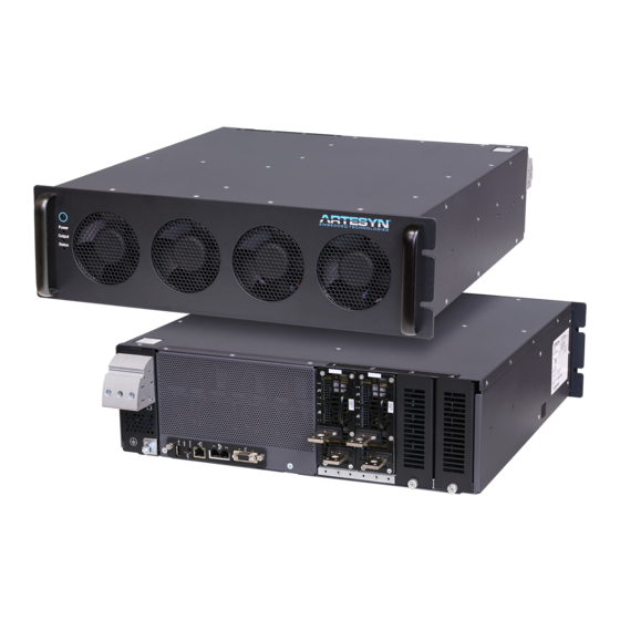
The basic modular concept consists of an iHP rack into which iHP modules are inserted. The rack is a Power Factor corrected front-end converting worldwide standard AC input voltages into a regulated high voltage DC (HVDC) output. -
Page 12: Specification Summary
Owners Manual The simplest way to get started is to use the Power Pro Connect Module (PPCM) to establish a link to the supply. The PPCM allows the user to quickly establish a connection with the power supply with a Web based GUI and set up the power supply. - Page 13 Owners Manual Table 1-2 iHP12 Electrical Specifications 19” Rack 12 KW Input strapped as 1-phase 19” Rack 12 KW strapped as 3-phase 19” Rack 12 KW strapped as 3-phase Parameter 200/220/230/240 Vac 200/208/240 Vac Nominal (iHP12L3A) 380/480 Vac Nominal (iHP12H3A)
-
Page 14: Table 1-1
Owners Manual Table 1-3 OUTPUT – General Specifications Parameter MODULE CODE # Outputs Nominal O/P (V) 12.0 V 24.0 V 48.0 V 80.0 V 125.0 V 200.0V 250.0 V Max Power (W) 2400 W 2880 W 3000 W 3000 W... -
Page 15: Environmental
Owners Manual 1.3.1 Environmental Table 1-4 outlines the operating and non-operating environmental requirements. Table 1-4 Environmental Specifications Operating Conditions ALL MODELS (Unless Otherwise Specified) Operating Temperature 0 °C to +50 °C at 100% rated load. Storage Temperature -40 °C to +85 °C. For Liquid Cooled models, liquid must be drained before storage... -
Page 16: Table 1-5
Owners Manual Table 1-5 OUTPUT – Module in Voltage Source Mode Voltage Source MODULE CODE Nominal Output (V) Setting 0.6 V - 14.4 V 1.2 V - 28.8 V 2.4 V - 57.6 V 4.0 V - 96.0 V 6.25 V - 150.0 V... -
Page 17: Table 1-6
Owners Manual Table 1-6 OUTPUT – Module in Current Source Mode Current Source - Programmable load compensation available for resistive and inductive loads; capacitive load applications; and LED drive applications MODULE CODE Nominal Output Setting Range 0.0 A - 200 A 0.0 A - 120 A... -
Page 18: Mechanical Outline
Figure 1-1 External dimensions of iHP system 1.3.4 Front and Rear Panel Figures 1-2 and 1-3 display the front and rear panels of iHP system. The user interface and connectors are shown. Note: Please Refer to Appendix A for the Front Panel LED response. -
Page 19: Figure 1-2 Front Panel Of Ihp System
Owners Manual Figure 1-2 Front panel of iHP system Figure 1-3 Rear Panel of iHP system iHP Manual 18 | P a g e... -
Page 20: Installation
The iHP system is inspected before packaging and is shipped in containers designed to minimize damage during transport. However, damage may still occur during transportation. Inspect the power supply and packaging upon receipt. If damage is observed that indicates the iHP system was dropped or subject to other damage, immediately notify the responsible shipping company. -
Page 21: Installation Requirements
Exposure to corrosive or conductive material can result to damage. iHP air-cooled units should have sufficient ventilation. The front and rear surfaces of the iHP system are recommended to have a minimum clearance of 2” from any airflow blockage. ... -
Page 22: Lifting Provision
Mounting The iHP rack is designed to fit inside a 19-inch rack. Recommended rack depth is at least 33 inches from front panel to back. The front panel cannot support the weight of the supply. Use appropriate L-brackets or an equipment tray, which can support the weight of the iHP system. -
Page 23: Figure 2-3 Module Insertion Into System
Owners Manual Caution! - Observe proper orientation of the module during insertion (output busbars at the bottom) to prevent damage to the module and rack connectors. Note: The input AC should be turned off for 5 minutes before inserting or removing modules from the rack. -
Page 24: Input And Output Wiring
Figure 2-4 Blank panel covering for rear of system 2.5 Input and Output Wiring Warning! - Disconnect AC power before wiring the iHP system. Due to possible remote operation, it is important to disconnect power at AC breaker before wiring the output connections. -
Page 25: Ac Input Wiring
Section 1.2.4. An appropriate ring terminal for M6 stud and the wire gauge must be used. The input configuration should be confirmed prior to wiring any AC power into iHP system. The figure below shows the location of the label to confirm the AC configuration. -
Page 26: Figure 2-5 Rear Panel Showing Ac Wiring And Ground Terminal
The rated input current and AC connection varies among different models. Table 2-2 shows the available models and rated input current. Table 2-2 iHP Rack Model Number Rated Current Wires to Connect 73-959-0001... -
Page 27: Dc Output Wiring
DC Output Wiring Wire output cables to each iHP module using M8 ring lugs, bolts, and nuts as shown in the Figure 2-7. The module output busbars are color coded with RED for positive (+) and BLUE for negative (-). -
Page 28: Remote Sense Wiring
2.5.3 Remote Sense Wiring The iHP system uses remote sense to regulate the voltage drops in the system. The module has a negative (V_SNS-) and a positive (V_SNS+) remote sense to compensate for line drops. Although not needed for operation, the remote sense wires must be connected to the desire regulated point to be able to meet the specification regulation limits. -
Page 29: Current Share Signal Wiring
Owners Manual Figure 2-8 Output modules in parallel with busbars 2.5.5 Current Share Signal Wiring For modules in constant voltage operation mode, the current share signals of all modules connected in parallel should be wired together. All ISHARE and D_RTN should be connected. Refer to Section 4.2.1 for the location of the ISHARE and D_RTN signals in the module connector J2. -
Page 30: Output Blocking Diode And Antiparallel Diode Recommendation
Owners Manual Figure 2-9 Output modules in series and parallel Please see Table 2-4 as a guide for what modules can be connected in series and combined voltage limitation per safety isolation compliance. Table 2-4 Model Number Model Module Nominal... -
Page 31: Figure 2-10 Blocking Diode For Use When Connecting Modules In Parallel
Owners Manual The iHP modules can be used in a redundant parallel system by connecting the outputs together via OR-ing diodes. For good regulation the remote sense connections must be made after the OR-ing diode at the same point on the busbar or load. The remote sense leads should be the same length for each power supply and a twisted pair should be used for best noise immunity. -
Page 32: Figure 2-11 Antiparallel Diode For Use When Connecting Modules In Series
Owners Manual Table 2-5 Min Voltage Min Current Model Maximum Vf Use below recommended device or its equivalent Rating (V) Rating (A) 0.9V @ 160A IXYS: DSS 2x160-0045A (45V 2x160A) (Tj = 125degC) 0.9V @ 160A (Tj = 125degC) IXYS: DSS 2x160-0045A (45V 2x160A) 0.7V @ 80A (Tj = 125degC) -
Page 33: Digital Communication
Once ISOCOMM receives a command from the user, ISOCOMM will transmit the command to the module or PFC section of the iHP. If the user needs data from a module or PFC device, the module or PFC device will transmit data to the ISOCOMM and ISOCOMM will be the one to send data to the user. -
Page 34: Ihp Digital Communication Identifier
3.1 iHP Digital Communication Identifier To communicate to the iHP, the user needs to know the iHP address and the specific device inside the iHP system in which the user needs to communicate. ISOCOMM, installed modules and PFC devices function independently inside an iHP system and each device has its own device address as shown in Figure 3-2 and 3-3. -
Page 35: Ihp Address
Ethernet Address – depends on the configuration of iHP. IP setting can be Static or DHCP. For Static IP, this will need to be set to an unassigned IP address by the user before integration into a system. For DHCP, the router will assign an open IP address. -
Page 36: Internal Device Address Inside Ihp
Note: Module group configuration is discussed in Section 5.1.5 and module group functionality is discussed in Section 6. 3.2 iHP Commands The iHP command set is patterned from PMBus, but uses a proprietary transaction protocol. All PFC devices have a specific set of commands, all module devices have a specific set of commands, and the ISOCOMM device has a specific set of commands. -
Page 37: Interval Between User Commands
DHCP, which requires connection with a router to assign an IP address. If a router is not being used, the iHP will not have an IP address to allow communication, so the user will need to use the LAN RESET button to set the iHP to known state, which is static IP with IP address of 192.168.2.100. -
Page 38: Figure 3-4 Ihp System Connected Directly To The Pc (Static Ip)
Owners Manual The iHP rack can be connected to a PC directly using the static IP setting. When using the iHP system with static IP mode, the user computer may need to have a static IP as well to communicate. Details on setting the IP configuration is discussed in Section 5.1.3. -
Page 39: Figure 3-5 Ihp System Connected Using A Router Or Switch
Figure 3-5 IHP system connected using a router or switch Up to six iHP systems can be used on the same network at the same time. To communicate using a PC with multiple iHP systems, the user can use a router (static or DHCP IP) or switch (static IP) as shown in Figure 3-6. -
Page 40: Figure 3-6 Multiple Ihp Systems Connected To Pc Via A Router Or Switch
Owners Manual Figure 3-6 Multiple iHP systems connected to PC via a router or switch The recommended equipment for communicating with the iHP system via the Ethernet are as follows: 8-pin RJ45 cable Router or Switch iHP Manual... -
Page 41: Rs485 Communication
Flow control = None RS485/CAN Bus Terminator or 120Ω terminating resistors are required at both end terminals, PC and iHP rack. For multiple RS485 communication, the terminating resistor should be placed on the iHP rack farthest from the PC/Laptop. -
Page 42: Can Communication
CAN communication with 1Mbps baud rate. RS485/CAN Bus Terminator or 120Ω terminating resistors are required at both end terminals, PC and iHP rack. For multiple iHP CAN communication, the terminating resistor should be placed on the iHP rack farthest from the PC/Laptop. - Page 43 Owners Manual 9 Way PCB D-sub Connector Socket & D-sub Connector Back shell RS485/CAN Bus Terminator – RJ11 with 120 ohms resistor (ARTESYN P/N: TBD) iHP Manual 42 | P a g e...
-
Page 44: Operation
GREEN color during the boot-up sequence. After boot-up sequence, the power LED will be either steady RED (AC BAD) or steady GREEN (AC OK) depending on the AC power to the iHP rack. For a full list of LED responses, please refer to Appendix A. -
Page 45: Ihp Module Default Settings
ISOCOMM will be functional. From the factory, when initially applying input AC, the iHP module outputs will not power-up by default and the user will need to press the front panel switch. The modules are shipped by Artesyn with Digital Voltage Source (DVS) configuration and the output voltage will be set to the module’s nominal voltage. - Page 46 Owners Manual Table 4-1 Default Configuration when shipped from Artesyn 12V Module 24V Module 48V Module 80V Module 125V Module 200V Module 250V Module User Command Parameter Configurable Process Process Process Process Process Process Process Data Data Data Data...
-
Page 47: Isocomm Default Settings
Owners Manual 4.1.3 ISOCOMM Default Settings Table 4.2 contains ISOCOMM default settings of the iHP rack when shipped from Artesyn. The ISOCOMM setting definition is in Section 5.1. Table 4-2 ISOCOMM WebTool Section User Default Setting when User Configurable... -
Page 48: Module Interface Signals
Figure 4-3 shows the location of the J1 and J2 connectors and the pin location of the signals. These signals allow direct interface with the supply to allow direct control and monitoring of the iHP system using analog and digital input and outputs. -
Page 49: Analog Voltage Programming
Owners Manual Use to control the output voltage by applying 0 to 10V 0-10VEXT_VPROG Input to this pin. This pin will function when the module is configured to Analog Voltage Source. Use to control the output voltage by applying 0 to 5V to... -
Page 50: Analog Current Programming
Owners Manual 2.5V 30% Nominal Output Voltage 60% Nominal Output Voltage 7.5V 90% Nominal Output Voltage 8.33V 100% Nominal Output Voltage 120% Nominal Output Voltage When utilizing signal, 0-5VEXT_VPROG, apply 0V to 5V between J1 pin 2 (0-10VEXT_VPROG) and J1 pin 8 (SYS_RTN). -
Page 51: Sys_Rtn
Module J2 D_RTN. 4.2.1.1.4 Isolated Output Inhibit The iHP module provides an input signal to inhibit the output. J1 Pin7 SYS_M_INHIBIT functions as the inhibit signal of the module. This inhibit pin is internally connected to an optocoupler’s LED side. An external 1kohms pull-up resistor is required. -
Page 52: Isolated Output Enable
Figure 4-4 Isolated output inhibit circuits to externally inhibit the module. 4.2.1.1.5 Isolated Output Enable The iHP module provides an input signal to enable output. J1 Pin 9 SYS_M_ENABLE# functions as the enable signal of the module. This pin is internally connected to an optocoupler’s LED side. An external 1kohms pull up resistor is required. -
Page 53: Isolated Fault Signal
Figure 4-5 Isolated Output Enable to externally Enable module. 4.2.1.1.6 Isolated Fault Signal During a fault condition, the iHP module provides a fault signal to the system side. J1 Pin 10 SYS_M_FAULT# functions as the fault signal of the module. The signal is internally connected to an open collector output. -
Page 54: Module's J2 Signal
Owners Manual Figure 4-6 Isolated fault signal to signal a module fault condition 4.2.1.2 Module’s J2 Signal Table 4-8 list the signal information available on connector J2. The module analog connector J2 contains non- isolated signals. The signal’s circuitry is internally connected and referenced to the module’s output negative terminal. -
Page 55: V_Sns+ And V_Sns
Owners Manual 4.2.1.2.1 V_SNS+ and V_SNS- The distance of the load and the module can create a voltage drop on the wires. To compensate for the voltage drops on the wire, remote sense is employed. The module has a positive return, V_SNS+ J2 Pin 1, and a negative return, V_SNS- J2 Pin 8, remotes sense to compensate for ground drops and line drops respectively. -
Page 56: External Current Sense
4.2.1.2.2 External Current Sense An external shunt resistor can be connected to the iHP module. The current sensing will be transferred from the iHP module internal shunt to external shunt. The iHP module’s EXT_ISENSE+ J2 Pin 3 and EXT_ISENSE- J2 Pin 9 signals are used for external current sense application. -
Page 57: Current Monitor (Imon)
Owners Manual When using external current sense, all output current information used by the iHP module will be taken from the differential voltage across the external shunt. The information collected from external sense connections will be used for output reporting, current protection, and constant current operation. -
Page 58: Voltage Monitor (Vmon)
Owners Manual Table 4-10 IMON Output Current 0% Nominal Output Current 2.5V 25% Nominal Output Current 50% Nominal Output Current 7.5V 75% Nominal Output Current Nominal Output Current 4.2.1.2.4 Voltage Monitor (VMON) VMON J2 Pin 11 is an output signal. VMON functions as the voltage monitor signal of the module. It reports the sensed output voltage with a scaled voltage between 0 and 0V. -
Page 59: Ihp Rack Communications And Interfaces
Figure 4-9 shows the back panel of the section and location of the ports and Table 4-12 list the available ports. Warning! - iHP rack signal in this section are isolated from module’s signal (J1 and J2 connector). -
Page 60: Usb Port
2 are the same. All signals with the same signal name of RS485/CAN port 1 and RS485/CAN port 2 are internally connected. The two ports functions to provide user easy iHP rack to iHP rack daisy chaining of the RS485 and CAN communication lines. -
Page 61: Gnd
Owners Manual 4.2.2.3.3 GND The GND is used as the common ground for RS485 or CAN communication. The GND signal is internally connected to DSUB9 pin 2 5V Housekeeping Bias Return. 4.2.2.3.4 5V Housekeeping Bias Supply Bias for CAN and RS485 communication and is internally connected to DSUB9 pin 1 5V Housekeeping Bias. -
Page 62: Housekeeping Bias
Owners Manual Table 4-13 DSUB9 Signal Name Signal Functions Type Pin No. 5V Housekeeping Bias Output 5V supply to power up system side circuits 5V Housekeeping Bias Output Ground reference of the 5V Housekeeping Bias Return Dummy Global Inhibit/Enable... -
Page 63: Global Inhibit/Enable Logic "0
Owners Manual A ground connection or no connection will de-activate Enable function and will shut down all modules 4.2.2.6.4 Global Inhibit/Enable Logic “0” The Global Inhibit/Enable Logic “0” (DSUB9 Pin5) signal functions to turn-off or turn-on all modules simultaneously. -
Page 64: Acok Signal "Power Fail" (Uncommitted Transistor)
Owners Manual 4.2.2.6.5 ACOK Signal “Power Fail” (Uncommitted Transistor) This signal indicates that the input AC is within operational range of the unit. ACOK- “Emitter” and ACOK+ “Collector” signal functions as an AC OK signal. These signals are connected to an uncommitted transistor. -
Page 65: Module Operating Mode
Figure 4-13 Possible circuits configuration for DCOK functionality At iHP rack start-up, the iHP rack will detect the slots with populated modules. The assertion of hardware DCOK signal will be based on the output status of the modules detected by the iHP rack during start-up. For example: When seven modules inserted to the iHP rack, ... -
Page 66: Digital Control
Owners Manual Analog Current Source (ACS) - The module operates as a current source. The module output current can only be controlled by inputting 0V-10V to module’s 0-10VEXT_IPROG signal (module J1 connector pin3) or 0V-5V to module’s 0-5VEXT_IPROG signal (module J1 connector pin4). -
Page 67: Table 4-17
Owners Manual will re-initialize, the Module Operational Command (01h) and Module Write Protect Command (10h) will be set to enable. The module output will be ON and set to nominal V out. Table 4-17 lists the status of the module command and the functionality of the commands when configuring the module to DVS mode. -
Page 68: Dvs Protection Modes
Owners Manual Setting the VREF outside the valid range: Setting the VREF value beyond the acceptable range, but not to 0V, the module will trigger a Status CML (Communication Memory Logic) fault and will retain the existing value. -
Page 69: Dvs Short Circuit Protection
Owners Manual Note that the CC setting level, IREF, will be reflected on IREF (Module Command B2h). When 52h is set to Latch Type, the module will shut down when the output current reaches the Latch Level for 500msec and a fault status will be reported. The Latch Current Level setting is dependent on the Vout setting (VREF). -
Page 70: Digital Current Source (Dcs)
Owners Manual 4.4.2 Digital Current Source (DCS) In this operating mode, user has the capability to control the output current using digital means. A PC or laptop will be required to change the output current. To change to Digital Current Source (DCS) mode, the user needs to send below commands to ISOCOMM. -
Page 71: Dcs Protection Modes
Owners Manual To change module output current, user needs to send below B2h (IREF) command to the module. Device Address Module Command Data <Module Slot Address> < Data is the Set Current> *Before writing to the module, please ensure that the Module Command Write Protect (10h) is disabled. -
Page 72: Dcs Protection: Over Voltage Protection (Ovp)
Owners Manual 4.4.2.1.3 DCS Protection: Over Voltage Protection (OVP) Over voltage protection level during DCS will be based on the OV Fault Limit Multiplier (48h) and VREF (B1h) setting. OV Level = (48h OV_FAULT_LIMIT_MULTIPLIER) x (B1h VREF) The module will shut down when the output voltage reaches the OVP level and a fault status will be reported. -
Page 73: Dvs Parallel Connection Protection
Owners Manual retain the existing value. Setting the VREF value to 0V, the module will enter to standby mode. To enable again the module, set VREF to an acceptable range. During group module change of output voltage: All modules in the group will adjust based on the commanded output voltage. - Page 74 Owners Manual Table 4-18 Model Min Voltage Min Current Maximum Vf Use Below Recommended Device or Rating (V) Rating (A) its Equivalent 0.9V @ 160A (Tj = IXYS: DSS 2x160-0045A (45V 125degC) 2x160A) 0.9V @ 160A (Tj = IXYS: DSS 2x160-0045A (45V...
-
Page 75: Dvs Series Connection Protection
Owners Manual IREF will automatically readjust if the voltage request is above the nominal output voltage. This will prevent module to operate above the rated power. 4.4.3.2.1 DVS Series Connection Protection Each individual module in a group will protect independently, as stated in Section 4.4.1. -
Page 76: Analog Control
Owners Manual 4.5 Analog Control The module’s output (output voltage or current) can be controlled using an external supply connected to the modules’ IPROG (0-10VEXT_IPROG or 0-5VEXT_IPROG) or VPROG (0-10VEXT_VPROG or 0-5VEXT_VPROG) signal. Definition of module is in Appendix B.2 Module Command. Definition of ISOCOMM Command is in Appendix B.3 ISOCOMM Command. - Page 77 Owners Manual Table 4-19 Module Command Name Functional Upon Change to AVS Command in AVS VREF Fix to Module's Nominal Output Voltage IREF During 52h set to Constant Current, value will be set based on Module Command 4Dh and nominal output current.
-
Page 78: Avs Protection Modes
Owners Manual 4.5.1.1 AVS Protection Modes When the supply is in AVS mode, the output is protected against over current, short circuit, over voltage, and under voltage faults. The behavior of the supply during an over current fault or short circuit fault is dependent on whether IREF is set to constant current behavior or latch behavior. -
Page 79: Avs Short Circuit Protection
Owners Manual Vo (VREF) is above the nominal voltage, Latch Level value is automatically reduced to maintain the supply within the maximum peak power of the module Latch Current Level = [ (Pnominal) * (OC_FAULT_LIMIT_MULTIPLIER)] / VREF Note that the latch setting level will NOT be reflected to IREF (Module Command B2h). Latch level can be determined by computation as stated above. -
Page 80: Table 4-20
No change from previous value SET_IO_ACTIVE_LEVEL_LOGIC No change from previous value SET_MODULE__LOAD_TYPE Last user B8h command. Artesyn Factory setting of DCS is Resistive (01h). ANALOG_FILTER_ENABLE No change from previous value *Functional: If Yes, command register is operational during the module mode. -
Page 81: Acs Protection Modes
Owners Manual 4.5.2.1 ACS Protection Modes When the supply is in ACS mode, the supply limits the current to the IREF value and the voltage is limited by the VREF value. Secondary output protection is provided in rare load conditions by the OC fault level and the OV fault level. -
Page 82: Avs Parallel Connection
Owners Manual AVS parallel connection AVS series connection ACS parallel connection To work properly, user needs to group the modules connected in parallel or series. To work properly, the modules must be connected in parallel or series. Only modules of the same model can be connected in series or in parallel. -
Page 83: Avs Parallel Connection Protection
Owners Manual have “0-10VEXT_VPROG” signals (Module’s J1 pin 1) star connected If user will operate using 0- 10VEXT_VPROG. have “0-5VEXT_VPROG” signals (Module’s J1 pin 2) star connected if user will operate using 0- 5VEXT_VPROG. connect external reverse biased (anti-parallel) diode to each module output. -
Page 84: Avs Series Connection Protection
Owners Manual have positive terminals connected in parallel. have negative terminals connected in parallel. have “SYS_RTN” signals (Module’s J1 Pin8) star connected. have “0-10VEXT_VPROG” signals (Module’s J1 Pin1) star connected if system will be operating using 0- 10VEXT_VPROG. -
Page 85: Configuration
Firmware section contains information to perform a firmware update. Maintenance section contains information to initiate System Reset. To access the ISOCOMM WebTool, open the web browser and type the iHP rack IP address to access the WebTool. The home page will be displayed. iHP Manual... - Page 86 Owners Manual User needs to enter USERNAME and PASSWORD when accessing below section (applicable to ISOCOMM SW v03.00.00) Rack section Module section Firmware section Maintenance section iHP Manual 85 | P a g e...
- Page 87 Owners Manual Default setting when shipped from Artesyn: User Name: admin Password: rtsn1234! When the user changes a setting, press “Save” button and perform System Reset. “Save” button is applicable only on the specific WebTool section. Meaning if user changes a parameter in a WebTool section, the “Save”...
-
Page 88: Home Section
Owners Manual 5.1.1 Home Section The Home Section contains a general summary of the iHP unit. WebTool Home section will display the following information ISOCOMM MAC Address IP Address Comms Firmware version PFC1 and PFC2 Firmware version... -
Page 89: Home Page Isocomm Section
Owners Manual 5.1.1.1 Home Page ISOCOMM Section 5.1.1.2 Home Page Module Section Each iHP rack slot’s module model number Each iHP rack slot’s module firmware version 5.1.1.3 Home Page Racks Section Racks connected (applicable to ISOCOMM SW v03.00.00) ... -
Page 90: Network Section
Owners Manual In below screen shot, there are three iHP rack in multi-rack operation. The WebTool will display the IP address of the other two racks connected. 5.1.2 Network Section Network configuration can be done using this section in the WebTool. The Network Section contains the following information: ... -
Page 91: Dhcp
This will allow user to enable or disable Dynamic Host Configuration Protocol. Setting Remarks Enable The router will automatically assign the IP address to the iHP rack. Once the setting is activated, user will need to search for the IP address assigned by the router. Disable IP address will be set to Static IP. -
Page 92: Rack Section
Owners Manual Address 2 Address 3 Address 4 Address 5 CAN broadcast address is set to address seven. RS485 does not have any broadcast address. 5.1.3 Rack Section Configuration of rack-related parameters can be updated in this WebTool section. -
Page 93: Power-Up Sequence
Send ISOCOMM Command: 01h Operational Command; Data: 80h Command to turn on the module. Note: Module turn-on will still be dependent on hardware inhibit or enable signals of iHP rack or iHP module. 5.1.3.3 INH0/EN0 TTL and INH1/EN1 TTL Function This configuration allows the user to configure: ... -
Page 94: Disable On 5V_Stby Fault
Floating Floating Floating 5.1.3.4 Disable on 5V_STBY Fault User can configure the iHP rack to disable the modules if 5V_Stby fault occurred. Setting Remarks Enable Once the 5V_Stby fault occurred, modules will be disabled. Disable Once the 5V_Stby fault occurred, modules are still enabled. -
Page 95: Module Section
Allowable racks to be synchronized is up to six racks. 5.1.4 Module Section In this section, user can configure multiple modules installed in the iHP rack as one. iHP Manual 94 | P a g e... -
Page 96: Module Synchronized Off
Owners Manual 5.1.4.1 Module Synchronized OFF This function will shut down all modules installed in an iHP rack when any module is at fault or in standby mode. User can configure this function. Setting Remarks Enable All modules installed in the iHP rack will shut down when any module is at fault or in standby mode. -
Page 97: Module Group
Power on AC source based on the input configuration of the unit. Unit will be operational after 20 seconds boot-up. Open Google Chrome Browser. Type the IP address of the iHP to proceed with the iHP WebTool page. iHP Manual 96 | P a g e... - Page 98 Owners Manual 1. Click “FIRMWARE” tab. 2. If asked for username and password, type below: User Name: admin Password: rtsn1234! 3. Upload the desired FW file. Click “Choose File.” iHP Manual 97 | P a g e...
- Page 99 Owners Manual 4. Select firmware file then click “Open”. Firmware file extension name is “.S” 5. Click “Upload File” iHP Manual 98 | P a g e...
- Page 100 Owners Manual 6. Once uploaded successfully, confirmation will be display as below. 7. Refresh WebTool. 8. The uploaded file should now be visible in the Available Firmware box. 9. Select the preferred device (i.e., PFC or Module 1 or Module 2, … or Module 8) to upgrade.
- Page 101 Owners Manual 10. Select the desired firmware to be bootloaded at the Available Firmware box. It should be highlighted as below. 11. Click “Flash selected firmware” to start the bootloading. Bootloading progress will be displayed. 12. The WebTool will notify the user once the bootloading is completed.
-
Page 102: Maintenance Section
Owners Manual 17. Go to WebTool Home page to check the FW version. 18. Turn-off Input AC. Firmware version checking is now complete. Note: ISOCOMM WebTool will prevent module firmware from programming PFC devices. ISOCOMM WebTool will prevent PFC firmware from programming module devices. -
Page 103: Ihp Module User Configurable Parameters
After 20 seconds, ISOCOMM is now configured to the new setting and operational. Note: When “Reset System” is initiated, this will only reset the ISOCOMM. 5.2 iHP Module User Configurable Parameters Definition of Module Command is located on Appendix B.2 Module Command. -
Page 104: Module Command 01H: Module_Operation
The OV_FAULT_LIMIT_MULTIPLIER function is dependent on the module mode. Please refer to Section 4.3 for the function of OV_FAULT_LIMIT_MULTIPLIER with respect to module mode. OVP Level = VREF + (Nominal Voltage * (OV_FAULT_LIMIT_MULTIPLIER – 1)) Example Module = 48V iHP Module Module Nominal Voltage = 48V Set VREF = 35V OV_FAULT_LIMIT_MULTIPLIER = 125% OVP Level = VREF + (Nominal Voltage * (OV_FAULT_LIMIT_MULTIPLIER –... -
Page 105: Module Command 4Dh: Oc_Fault_Limit_Multiplier
Section 4.3 for the function of OC_FAULT_LIMIT_MULTIPLIER with respect to module mode. Set Vo (VREF) is below or equal to the nominal voltage OC Level = (Inominal) * (OC_FAULT_LIMIT_MULTIPLIER) OC response will be Module = 48V iHP Module Module Nominal Current = 62.5A VREF = 48V OC_FAULT_LIMIT_MULTIPLIER = 75% OC Level = (Inominal) * (OC_FAULT_LIMIT_MULTIPLIER) OC Level = (62.5) * (0.75) -
Page 106: Module Command B7H: Set_Io_Active_Level_Logic
Owners Manual Data 00h – Constant current over current response Data 01h - Latch Type over current response The OC_RESPONSE_TYPE function is dependent on the module mode. Please refer to Section 4.3 for the function of OC_RESPONSE_TYPE with respect to module mode. - Page 107 Owners Manual Module Mode Module Command B1h Function Digital Voltage Source Output voltage of the module can be change using this command. Digital Current Source Functions as output voltage clamp level during current source operation. Analog Voltage Source Module below SW v04.15: Fix to nominal voltage. Cannot be changed.
-
Page 108: Module Group
Owners Manual Module Group Module Group function was designed to treat multiple modules in a rack as one. The main function of module grouping is to provide a: 1. Single command for all modules in a group (limited command). -
Page 109: Group Initialization At Start Up
If there are discrepancies in the module configurations, all iHP modules in the iHP rack will not be allowed to turn-on. ISOCOMM command 80h (MFR Status) low byte bit 4 will be asserted (Group Mismatch Fault). -
Page 110: Accepted Group Commands Using Group Device Address
Owners Manual 6.5 Accepted Group Commands using Group Device Address Command Command Name OPERATION CLEAR_FAULTS WRITE_PROTECT OV_FAULT_LIMIT_MULTIPLIER UV_FAULT_LIMIT_MULTIPLIER OC_FAULT_LIMIT_MULTIPLIER OC_RESPONSE_TYPE VREF IREF SET_IO_ACTIVE_LEVEL_LOGIC ANALOG_FILTER_ENABLE Above commands have the same function as specified in Appendix B.2 Module Command. When users send above WRITE command with Group address, all modules included in that Group will receive the WRITE command at the same time. - Page 111 Owners Manual Command Command Name Remarks 0x7Ah STATUS_VOUT ISOCOMM will read each module STATUS_VOUT reporting. ISOCOMM will perform OR operation of STATUS_VOUT of all modules belonging to the group. 0x7Bh STATUS_IOUT ISOCOMM will read each module STATUS_IOUT reporting. ISOCOMM will perform OR operation of STATUS_IOUT of all modules belonging to the group.
- Page 112 Owners Manual Command Command Name Remarks ISOCOMM will read each module output current reporting. ISOCOMM will average the reported output current of the modules in the group. 0x8Dh READ_TEMPERATURE_1 ISOCOMM will read each module temperature reporting. ISOCOMM will report the highest temperature reading of the modules in the group.
-
Page 113: Multi-Rack Operation
Ethernet communication as it uses Ethernet communication to perform this function. All IP addresses of the iHP rack, router and PC should be the same except for the last octet. For example, each IP address will start at 192.168.2.xxx and each iHP rack, router and PC will have a unique value for xxx (except for 0 and 255) The following diagram shows the system configuration for Rack Synchronization OFF Ethernet communication. -
Page 114: During Turn-On
Using Power SW button located in the front panel. 7.1 During Turn-On iHP rack with Rack Synchronization OFF enabled will communicate to each other via Ethernet. Each iHP rack will get all the IP addresses (for Ethernet) of all rack with enabled Rack Synchronization OFF. This will be recorded in the ISOCOMM WebTool. -
Page 115: During Turn-Off
7.2 During Turn-off o iHP rack with fault or standby will send a “FAULT/STANDBY” status via Ethernet. Once the iHP rack receives the “FAULT/STANDBY” status, each iHP rack will shut down all modules. After this, the iHP rack with Fault or Standby status will continue to broadcast the “FAULT/STANDBY”... - Page 116 Owners Manual Above sample Multi Rack operation is using 2 units of iHP 12KW Rack with two modules each inserted per Rack. The 2 modules, Module 1 & Module 2 are group in Group 1. Broadcast address is set at 192.168.2.255.
-
Page 117: Faults And Output Recovery
Owners Manual Faults and Output Recovery. 8.1 Module Fault Fault Description This fault will be trigger when module output increases beyond or equal to the Output Voltage Over set Over Voltage Fault level. Voltage Fault. Over Voltage Fault level will be based on Module Command 48h. -
Page 118: Module Clear Fault And Output Recovery
Owners Manual Fault Description Please refer to Section 3.1.2 for iHP Module Configuration Default Settings for the over temperature level and recovery. Module Over Temperature Occurrence of over temperature warning in the module. Unit will NOT Warning shutdown once the module internal device reaches the over temperature warning level. -
Page 119: Pfc Fault
Module Faults will be clear and module will re-start to power up again once user Turn-off then turn-on the module via iHP rack “Global Inhibit/Enable Logic 1” signal Turn-off then turn-on the module via iHP rack “Global Inhibit/Enable Logic 0” signal 5. - Page 120 Owners Manual Fault Description PFC receives invalid or unsupported Data. Invalid or Unsupported PFC will NOT shutdown. Data Received User needs to send Clear Fault command to PFC in order to remove the fault. Packet Error Check PFC-ISOCOMM communication data error.
-
Page 121: Pfc Clear Fault And Output Recovery
Owners Manual 8.4 PFC Clear Fault and Output Recovery Methods of PFC Clear Fault and Output Recovery are as follows 1. PFC Command 03h “CLEAR_FAULT” When this command is received by the PFC, the PFC will clear all faults in the PFC Command Status. -
Page 122: Isocomm Fault
Occurrence of high ambient temperature in the iHP rack. Ambient Over Temperature Fault All modules in the iHP rack will shut down once the ambient temperature reaches the over temperature level. Over Temperature Fault will be auto-cleared and module output will recover once the temperature is below the set ambient over temperature less 5 Please refer to Section 5.1.4.1 for the ambient over temperature level setting... -
Page 123: Isocomm Clear Fault And Output Recovery
Owners Manual Fault Description Module Synchronize Off Occurrence of any fault in a module when user configurable parameter “Module Synchronize OFF” is enabled. Module/s will shut down. Please refer to Section 8.6 for the clear fault and output recovery. - Page 124 Owners Manual 3. ISOCOMM Fault can be cleared and output will recover after turn-off, then turn-on the iHP unit using Front Panel STBY Switch. iHP Manual 123 | P a g e...
-
Page 125: Accepted Ihp Configuration
Owners Manual Accepted iHP Configuration iHP power system is a configurable power supply. Modules can be configured in series or in parallel operation. There are safety considerations to observe when modules are configured. Modules can be categorized into Safety Extra Low Voltage (SELV) or Non–Safety Extra Low Voltage (non-SELV). -
Page 126: Parallel Configuration
9.2 Parallel Configuration Inter Rack Module parallel operation is acceptable (up to 6 iHP racks) and only same type of modules can be connected in parallel. SELV and Non-SELV modules can be co-located in a single iHP rack to meet Medical MOOP safety spacing provided that co-located module series connected should have a total output voltage of equal or less than 800V. -
Page 127: Series Configuration
73-936-0250 300V Medical MOOP SELV Module cannot be co-located with above 800V output (series connected module). iHP rack setting during Inter Rack Parallel Operation. MODULE SYNCRONIZED Off should be enable Module Grouping should be the same in each rack ... - Page 128 Owners Manual Module Grouping should be the same in each rack RACK SYNCRONIZED OFF should be enable Series Operation Safety Accessibility Restrictions Secondary Signal and Power Output Section Series up to Series up to Series up to...
- Page 129 Owners Manual Isolated Secondary Signal Output Series ISOLATED SECONDARY Signal Output Configuration Safe to Access Not Safe to Access Requires Enclosure Maximum Vo of Co-located Module Maximum Vo of Co-located Module Series Connected Maximum Vo of Series Series Connected...
-
Page 130: Troubleshooting
Owners Manual Troubleshooting Use below table as an aid in troubleshooting iHP system. Symptom Check Action No Output. Is the input wire defective? Check continuity or measure input All front panel LEDs are OFF. voltage on the iHP input terminal block. - Page 131 Owners Manual Symptom Check Action Module output out of regulation Have you check reported current Adjust output loading as module during DVS mode, no faults or output loading? may have entered current limit. reported except Module Power_Good# (79h 0008h...
-
Page 132: Appendix A - Led
Owners Manual Appendix A – LED iHP Front Panel LED iHP front panel LEDs are composed of Power LED Output LED Status LED Please see below front panel LED response Condition POWER LED OUTPUT LED SYSTEM STATUS LED... -
Page 133: Appendix B -Command
Owners Manual Appendix B –COMMAND B.1 PFC Command To convert Linear Data Format to “real world value”, please refer to Appendix B.4 To convert Direct Data Format to “real world value”, please refer to Appendix B.5 PFC Command Definition... - Page 134 Owners Manual Command Command Name Definition Code Bit # Status Bit Name Supported VOUT IOUT/POUT INPUT MFR_SPECIFIC POWER_GOOD# FANS OTHER UNKNOWN STATUS_VOUT Same as standard PMBUS_STATUS_VOUT Register. Command returns one data byte with contents as follows: Bit # Status Bit Name...
- Page 135 Owners Manual Command Command Name Definition Code Reserved Reserved Reserved Reserved STATUS_CML Same as standard PMBUS_STATUS_CML Register. Command returns one data byte with contents as follows: Bit # Status Bit Name Supported Invalid or Unsupported Command Received Invalid or Unsupported Data Received...
- Page 136 Owners Manual Command Command Name Definition Code Bit13 Reserved Bit12 Reserved Bit11 Vin3OVP Bit10 Vin2OVP Bit9 Vin1OVP Bit8 Vin3UVP Bit7 Vin2UVP Bit6 Vin1UVP Bit5 Bit4 Relay Bit3 Supply Bit2 PSON Bit1 Address Bit0 BulkOK Index 01 “PFC Status” Bit Name...
-
Page 137: Module Command
Block Read 2 bytes per Bitmapped index Note: 24kW iHP rack is composed of two boards of 12kW PFC. In PFC PMBUS Commands, IOUT refers to the Output current of the PFC in which the command is addressed. ... - Page 138 Owners Manual To convert Linear Data Format to “real world value”, please refer to appendix B.4 To convert Direct Data Format to “real world value”, please refer to appendix B.5 MODULE Command Definition Command Code Command Name Definition OPERATION Same as standard PMBUS_OPERATION Register.
- Page 139 Owners Manual Command Code Command Name Definition POUT_MAX Read Module’s rated power Refer to Module Command data classification for Data Format MFR_REG Manufacturer register. Do not access. VOUT_OV_FAULT_RESPONSE Same as standard PMBUS_VOUT_OV_FAULT_RESPONSE Register. Read Module Response during over-voltage fault condition Fix Data: 80h –...
- Page 140 Owners Manual Command Code Command Name Definition OV_FAULT_LIMIT_MULTIPLIER Data is used to compute for the tracking over voltage protection (OVP) of the module Refer to Module Command data classification for Data Format. During Digital Voltage Source (DVS), Analog Current Source (ACS), and Digital Current Source (DCS).
- Page 141 Owners Manual Command Code Command Name Definition UV_FAULT_LIMIT_MULTIPLIER Data is used to compute for the under voltage protection (UVP) level of the module Refer to Module Command data classification for Data Format. Under Voltage Protection is functional during Digital Programming Voltage Source (DVS) UVP Level = VREF –...
- Page 142 Owners Manual Command Code Command Name Definition OC_FAULT_LIMIT_MULTIPLIER Data is used to compute for the Over Current Protection (OCP) level of the module Refer to Module Command data classification for Data Format. Digital Voltage Source and Analog Voltage Source...
- Page 143 Owners Manual Command Code Command Name Definition OT_WARN_LIMIT Over Temperature Warning level of the Module for TEMP1. Refer to Module Command data classification for Data Format. Fix data varies per module series. OC_RESPONSE_TYPE Command to read/write Over-current Protection Type Applicable only during Voltage Source configuration.
- Page 144 Owners Manual Command Code Command Name Definition MFR_REG Manufacturer register. Do not access. MFR_REG Manufacturer register. Do not access. MFR_REG Manufacturer register. Do not access. MFR_REG Manufacturer register. Do not access. STATUS_BYTE Standard PMBUS STATUS Register. Returns one byte of information with the summary of the most critical Module faults.
- Page 145 Owners Manual Command Code Command Name Definition STATUS_WORD Same as standard PMBUS_STATUS_WORD Register. Returns two byte of information with the summary of the Module’s faults condition. Based on the information, User can get more information by reading the appropriate status registers.
- Page 146 Owners Manual Command Code Command Name Definition STATUS_VOUT Same as standard PMBUS_STATUS_CML Register. Command returns one data byte with contents as follows: Bit # Status Bit Name Supported VOUT Overvoltage Fault VOUT Overvoltage Warning VOUT Undervoltage Warning VOUT Undervoltage...
- Page 147 Owners Manual Command Code Command Name Definition STATUS_INPUT Same as standard PMBUS_STATUS_INPUT Register. Command returns one data byte with contents as follows: Bit # Status Bit Name Supported VIN Overvoltage Fault VIN Overvoltage Warning VIN Undervoltage Warning VIN Undervoltage Fault...
- Page 148 Owners Manual Command Code Command Name Definition STATUS_CML Same as standard PMBUS_STATUS_CML Register. Command returns one data byte with contents as follows: Bit # Status Bit Name Supported Invalid or Unsupported Command Received Invalid or Unsupported Data Received Packet Error Check Failed...
- Page 149 Owners Manual Command Code Command Name Definition STATUS_MFR_SPECIFIC Same as standard PMBUS_STATUS_MFR_SPECIFIC Register. Command returns one data byte with contents as follows: Bitmap: Bit7: MFR Specific Fault Bit6: Reserved Bit5: Asserted when DSP supply goes below regulation Bit4: Reserved...
- Page 150 Owners Manual Command Code Command Name Definition MFR_ID Same as standard PMBUS_MFR_ID Register. Command to indicate the manufacturer’s Identification. Fix data: “ARTESYN” MFR_MODEL Same as standard PMBUS_MFR_MODEL Register. Command to indicate the manufacturer’s model number. Data : Varies per module series...
- Page 151 Owners Manual Command Code Command Name Definition MFR_VOUT_MAX Same as standard PMBUS_MFR_VOUT_MAX Register. Maximum Output voltage that can be set in the Module. Refer to Module Command data classification for Data Format. MFR_IOUT_MAX Same as standard PMBUS_MFR_IOUT_MAX Register. Maximum Output current that can be set in the Module.
- Page 152 Owners Manual Command Code Command Name Definition VREF Module voltage reference. Refer to Module Command data classification for Data Format. Command have different function in each Module operation (D3h) Digital Voltage Source o User Configurable. User can change output voltage using this command from 5% of nominal Vout to 120% of nominal Vout.
- Page 153 Owners Manual Command Code Command Name Definition IREF Module current reference. Refer to Module Command data classification for Data Format. Digital Current Source o User Configurable. User can change output current using this command from 0A to Nominal output current.
- Page 154 Owners Manual Command Code Command Name Definition SET_VOLTAGE_RISE_SETTING Command used to read the voltage rise time during Module’s Digital Voltage Source (DVS) operation. Data Range: 00h – 0Fh Data 0x00h: 10ms (+/- 5msec) Data 0x01h: 20ms (+/- 5msec) Data 0x02h: 50ms (+/- 5ms)
- Page 155 Owners Manual Command Code Command Name Definition SET_CURRENT_RISE_ SETTING Command used to read the current rise time during Module’s Digital Current Source (DCS) operation. Data Range: 00h – 0Fh Data 0x00h: 7.2ms Data 0x01h: 100ms (+/- 10ms) Data 0x02h: 125ms (+/- 10ms)
- Page 156 Owners Manual Command Code Command Name Definition SET_IO_ACTIVE_LEVEL_LOGIC Command used to set the logic of SYS_M_FAULT#, SYS_M_ENABLE#, and SYS_M_INHIBIT signals. Bitmap: Bit7: Reserved Bit6: Reserved Bit5: Reserved Bit4: Reserved Bit3: Reserved Bit2: Data: 1 – SYS_M_FAULT# Logic High means Module is at Fault.
- Page 157 Owners Manual Command Code Command Name Definition ANALOG_FILTER_ENABLE To enable or disable heavy filtering of IPROG signal during ACS or VPROG signal during AVS. Bit2 to7: Reserved/Unused Bit1: Data “1” ACS Heavy Filter Enabled Data “0” ACS Heavy Filter Disabled Bit0: Data”1”...
- Page 158 Owners Manual Command Code Command Name Definition SHUTDOWN_CAUSE Status that indicate the cause of Module shutdown Bitmap: Bit 4-6: Reserved/Unused Bit3: Config Inhibit Status : Module inhibit status during Module Configuration change. Bit 2: Module is ON (1), Module is OFF (0)
- Page 159 Owners Manual Command Code Command Name Definition MODULE_CONFIG Command to Read Module Configuration Mode Bitmap: Bit 7-4: Reserved/Unused Bit 6: Reserved Bit 5: Reserved Bit 4: Reserved/Unused Bit 3: Source Selection Data 1: Current Source Mode Data 0: Voltage Source Mode...
- Page 160 OPTN_TIME_TOTAL Command to read the total time when the Module is turn-on and the output is operational. This will reset when the iHP Rack is turn-off. OPTN_TIME_PRESENT Command to read the total time when the Module is turn-on and the output is operational.
- Page 161 Owners Manual Module Command Data Classifications Command Command Name Transaction # of Data Multiplier Data Write Type Bytes Format Unit Protection OPERATION Read/Write Bitmapped Basic Byte CLEAR_FAULTS Send Byte Basic WRITE_PROTECT Read/Write Bitmapped None Byte VOUT_MAX Read Word DIRECT...
- Page 162 Owners Manual Command Command Name Transaction # of Data Multiplier Data Write Type Bytes Format Unit Protection STATUS_WORD Read Word Bitmapped STATUS_VOUT Read Byte Bitmapped STATUS_IOUT Read Byte Bitmapped STATUS_INPUT Read Byte Bitmapped STATUS_TEMPERATURE Read Byte Bitmapped STATUS_CML Read Byte...
-
Page 163: Isocomm Command
Owners Manual Command Command Name Transaction # of Data Multiplier Data Write Type Bytes Format Unit Protection SET_VOLTAGE_RISE_SETTING Block Read Direct Word SET_CURRENT_RISE_SETTING Block Read Direct Word SET_IO_ACTIVE_LEVEL_LOGIC Block Bitmapped Basic Read/Write SET_MODULE_LOAD TYPE Block Read Bitmapped Word ANALOG_FILTER_ENABLE... - Page 164 Owners Manual Command Command Name Definition Code OPERATION Command used to Turn-off or Turn-on ALL modules. Bit 7 = 1 : Module is ON Bit 7 = 0 : Module is OFF Bit 0 to Bit 6 : Don’t Care User Configurable.
- Page 165 Owners Manual Command Command Name Definition Code FAN_CONFIG_3_4 Same as standard PMBUS_FAN_CONFIG_3_4 Register. Command returns one data byte with contents as follows: Bit # Status Bit Name Fixed data Supported Data 1: Fan 3 is present. Data 0: Fan 3 is not present.
- Page 166 Bit # Status Bit Name Supported OT_FAULT OT_WARNING UT_WARNING UT_FAULT Reserved Reserved Reserved Reserved ISOCOMM OTP protection is with reference to the ambient temperature of the iHP RACK (Front Panel Ambient Temperature). iHP Manual 165 | P a g e...
- Page 167 Owners Manual Command Command Name Definition Code STATUS_CML Same as standard PMBUS_STATUS_CML Register. Command returns one data byte with contents as follows: Bit # Status Bit Name Supported Invalid or Unsupported Command Received Invalid or Unsupported Data Received Packet Error Check Failed...
- Page 168 This command returns the highest temperature between PFC1 and PFC2. Refer to ISOCOMM Command data classification for Data Format READ_TEMPERATURE_2 This command returns the Ambient Temperature of the iHP Rack. Temperature sensor of the Ambient temperature is located on the Front panel.
- Page 169 Owners Manual Command Command Name Definition Code MODULE_VRISE_TIME Command used to set the voltage rise time of the module during Module’s Digital Programming Voltage Source (DPVS) operation. This command has 3 bytes of data to write <DATA1> <DATA2> <DATA3>...
- Page 170 Data “00 0F” : 1250ms (+/- 50ms) ending this PMBUS command, All modules will shut down and restart again. READ_VIN1 iHP RACK Input Voltage reporting (Vac) for Line1 Refer to ISOCOMM Command data classification for Data Format READ_VIN2 iHP RACK Input Voltage reporting (Vac) for Line2...
- Page 171 Command Name Definition Code READ_IIN1 iHP RACK Input Current reporting (Vac) for Line1 Refer to ISOCOMM Command data classification for Data Format READ_IIN2 iHP RACK Input Current reporting (Vac) for Line2 Refer to ISOCOMM Command data classification for Data Format...
- Page 172 Definition Code MODULE_DETECTION Command to indicate module present in the iHP RACK Data Bit0 : Asserted when module is present in slot1 Data Bit1 : Asserted when module is present in slot2 Data Bit2 : Asserted when module is present in slot3...
-
Page 173: Data Format: Linear
Owners Manual Command Command Name Transaction # of Data Multiplie Data Write Type Bytes Format Unit Protection STATUS_WORD Read Byte Bitmapped STATUS_TEMPERATUR Read Byte Bitmapped STATUS_CML Read Byte Bitmapped STATUS_MFR Read Byte Bitmapped STATUS_FAN_1_2 Read Byte Bitmapped STATUS_FAN_3_4 Read Byte... - Page 174 Owners Manual Data Format Linear is one of the PMBUS Data Format used in iHP units. Please refer to Appendix B.1, B.2, and B.3 for the PMBUS Commands that uses Linear Data Format. The Linear Data Format is a two byte value with: o An 11bit, two’s complement mantissa.
-
Page 175: Data Format: Direct
X= 88 B.5 Data Format: Direct One of the Data Format used in iHP units. Please refer to Appendix B.1, B.2, and B.3 for the Commands that uses Direct Data Format. In order to convert the data in to “real word” value, user needs to determine the # of bytes and the multiplier. - Page 176 Owners Manual X = 48.12 V Example 2 Module Command 8Ch (READ_IOUT) # of byte = 3 Byte Multiplier = N = 10000 COMMAND 8Bh returns a data of 098968h Convert 098968h to decimal = 625000 Y = X * N 625000 = X * 10000 X = 62.5A...
-
Page 177: Appendix C - Module Register Mfr_Reg (Fae And Var Only)
Owners Manual Appendix C – MODULE REGISTER MFR_REG (FAE and VAR only) MODULE Command Definition for MFR_REG Command Command Name Definition Code VOUT_OV_FAULT_LIMIT Command to Read the Voltage level of the Module OVP. Based on Module Command 48h. VOUT_OV_WARN_LIMIT Command to Read the Voltage level of the Module OVP Warn. - Page 178 Owners Manual Command Command Name Definition Code OC_WARN_LIMIT_MULTIPLIER Data is used to compute for the Over Current Warning (OCP) level of the module Refer to Module Command data classification for Data Format. Digital Voltage Source and Analog Voltage Source...
- Page 179 Owners Manual Command Command Name Definition Code IoutHigh_Sckt_Level During Current Source Mode, when the module's output current goes greater than or equal to IoutHigh_Sckt_Level, the module latches off when the output voltage level goes less than or equal to the VoutLow_SCKT_Level (53h) setting for the validation period (default: 2s).
- Page 180 Owners Manual Command Command Name Definition Code READ_TEMPERATURE_2 Read Module Cool Temp setting used by ISOCOMM Fan Control. PCSI Contains the active values for CONTROL LOOP settings. Be cautious in changing values. Can be written but values will not be saved.
- Page 181 Owners Manual Command Command Name Definition Code DSP_SOFTWARE RESET Command to re-initialize the Module DSP. o Disable Write Protect via Module command 10h o Send Admin access via Module command E2h o Turn-off the module either Module Operational Command ...
- Page 182 Owners Manual PCSI_DATA_CMD Contains the control settings for different load types. The corresponding settings from this register are loaded to B3h PCSI register during DSP initialization. Difference between B3h and D5h. B3h changes will be active during unit is power-on. When the unit shutdown and restart again the setting will revert back to the original.
- Page 183 Owners Manual Command Command Name Definition Code Bit 15- 5: Reserved/ Unused Bit 4: Memory Error Fault Auto Bit Bit4 Assertion due to User Settings Applied. Updated only in Initialization Bit 4 Deassertion: Writing in 0xF9 and 0xFA Command...
- Page 184 Owners Manual Command Command Name Definition Code CONFIG_DATA Contains the Module Housekeeping Configuration. User can Read the Module Housekeeping Configuration Read E4h (Offset) User can write the Housekeeping Configuration. Write Procedure -Turn-off the module either o Module Operational Command...
- Page 185 Owners Manual Command Command Name Definition Code CAL_COEF_DATA Register used to Read/Write Module Calibration Parameters o VPROG, IPROG IMON, TEMP1, and TEMP2 coefficient. o Voltage and Current programming reporting Factory default coefficient o Calibrated nominal setting VREF and IREF factory default setting.
- Page 186 Owners Manual Command Command Name Transaction # of Data Multiplier Data Write Type Bytes Format Unit Prtotection VOUT_OV_FAULT_LIMIT Read Word Direct 10000 VOUT_OV_WARN_LIMIT Read Word Direct 10000 VOUT_UV_WARN_LIMIT Read Word Direct 10000 VOUT_UV_FAULT_LIMIT Read Word Direct 10000 IOUT_OC_FAULT_LIMIT Read Word...
- Page 187 Owners Manual Command Command Name Transaction # of Data Multiplier Data Write Type Bytes Format Unit Prtotection CONFIG_UNLOCK_CODE Read/Write Basic Byte CONFIG_CTRL WRITE Byte Basic CONFIG_DATA Block Direct Factory Read/Write Config* READ_VOR Block Read Direct 10000 CAL_RAW_READ Block Read...
- Page 188 Owners Manual For ISOCOMM B8h SET_MODULE_LOAD_TYPE Command to read Module compensation data: 01h – Resistive load compensation Data: 02h - Capacitive load compensation Data: 04h - LED load compensation Module will not accept any data aside from the above listing.
- Page 189 Owners Manual Here are the settings of each module based on latest config (ini) file: 125V 250V VOR Clamp 1.087V 2.174V 3.6233V 6.0388V 11.4421V Brick Wall OVP 31.3V 64.5V 110V 162V 315V VOR clamp level based on actual module read back ...
-
Page 190: Appendix D - Fae And Var Only
Rack can operate on 3P Low Line (3P 187.5Vac to 264Vac) and 3P High Line (3P 342Vac to 528Vac). At any instance, the iHP RACK can operate only in one input line either 3P Low Line or 3P High Line. - Page 191 Owners Manual 3P Low Line Config Board 1P Config Board iHP Manual 190 | P a g e...
- Page 192 Owners Manual Required Tools for the Input Configuration Board Change. Torx screwdriver #15 Torx screwdriver #20 Input Configuration Board Screw Input Configuration Board screw is an M4 screw with 8mm length. Recommended screw for the Input Configuration Board iHP Manual...
- Page 193 Owners Manual Manufacturer Manufacturer Part Number BOSSARD 6166428 NISSHI METAL SCREW G-A01-B1589 Input Configuration Board Number of M4 Screw 3P Low Line Configuration 12pcs 3P High Line Configuration 9pcs Procedure to change the Input Configuration Board. Notes: Be sure that the unit is not connected to the input AC.
- Page 194 Owners Manual 12KW RACK iHP Manual 193 | P a g e...
- Page 195 Owners Manual 2. Remove Side Cover Screws Tool: Torx screwdriver #15 24KW RACK 12KW RACK 3. Push the Side cover upward then remove from the iHP RACK 24KW RACK iHP Manual 194 | P a g e...
- Page 196 Owners Manual 12KW RACK 4. Remove screw of the Config Label. Tool: Torx screwdriver #15 iHP Manual 195 | P a g e...
- Page 197 Owners Manual Push the Top cover near the Config Label upward. This will remove the Config Label. 6. Remove the screws in the Config Board. This will detach the config board from the iHP RACK. Tool: Torx screwdriver #20 Note: Number of screws for 3P Low Line Config Board and 3P High Line Config Board are not the same.
- Page 198 Owners Manual 8. Install the Config Board in the AC Interconnect Board using screw. Tool: Torx screwdriver #20 Note: Number of screws for 3P Low Line Config Board and 3P High Line Config Board are not the same 9. Push the Top cover near the Config Label upward. Then, insert the Config Label.
- Page 199 Owners Manual 10. Fix the Config Label via screw. Tool: Torx screwdriver #15 11. Config Label cabling harnessing. iHP Manual 198 | P a g e...
- Page 200 Owners Manual 12. Install the Side cover to the iHP RACK using screw. Tool: Torx screwdriver #15 Please take note the Alignment pin of the Side Panel to the iHP RACK. 24KW RACK iHP Manual 199 | P a g e...
- Page 201 Owners Manual 12KW RACK 13. Config Board Change Done. iHP Manual 200 | P a g e...
Need help?
Do you have a question about the iHP and is the answer not in the manual?
Questions and answers