Comar Systems CSB200 Installation And Instruction Manual
Class b ais transponder
Hide thumbs
Also See for CSB200:
- Installation and instruction manual (24 pages) ,
- Programming manual (10 pages)
Advertisement
Quick Links
Advertisement

Related Manuals for Comar Systems CSB200


Summary of Contents for Comar Systems CSB200
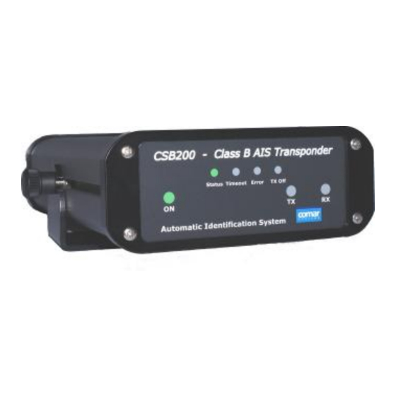
- Page 1 Installation Instruction Guide CSB200 Class B AIS Transponder...
- Page 2 CSB200 Class B AIS Table of Contents GENERAL WARNINGS……………………………………..3 INTRODUCTION……………………………………………...5 Automatic Identification Systems (AIS)……………….. 5 INSTALLING THE CSB200 UNIT………………………….6 Packing List…………………………………………………6 Electrical Connections…………………………………….6 GPS Antenna………………………………………………7 VHF antenna for AIS use………………………………...7 WARNINGS…………………………………………………8 PROGRAMMING THE TRANSPONDER………………….9 aisPRO Program…………………………………………..9 USING THE TRANSPONDER…………………………….11 Switching on………………………………………………11 Warning and Fault States………………………………11...
- Page 3 GENERAL WARNINGS Comar Systems Ltd is not responsible for damages or injuries caused by your use of or inability to use the CSB200 correctly. The CSB200 is intended for use only by persons trained in navigation and only as a...
- Page 4 In accordance with a policy of continual development and product improvement the CSB200 hardware and software may be upgraded from time to time and future versions of the CSB200 may therefore not correspond exactly with this manual. When necessary upgrades to the product will be accompanied by updates or addenda to this manual.
- Page 5 Class B units are currently not a mandatory fit but authorities in several parts of the world are considering this. Class B units are designed for fitting in vessels which do not fall into the mandatory Class A fit category. The CSB200 is a Class B unit R4.0...
- Page 6 1 x CD 1 x Instruction Manual WARNING: Do not connect the CSB200 unit to a mains (line) AC electrical supply, as an electric shock or fire hazard could result. CAUTION: Do not connect the CSB200 unit to a DC supply exceeding 15.6 V or reverse the supply polarity.
- Page 7 AIS unit; after subtraction of cable and connector losses a minimum total gain of 25 dB should be available at the CSB200 unit GPS antenna connector. The GPS antenna to be used for AIS use must be a dedicated antenna, i.e.
- Page 8 CSB200 Class B AIS bandwidth must cover the two AIS channels and the DSC Channel. Should be mounted with at least a two metre vertical separation distance from any other VHF antenna used for speech or DCS communication. WARNINGS...
- Page 9 CSB200 Class B AIS PROGRAMMING THE TRANSPONDER aisPRO Program Before the CSB200 can transmit it requires to be programmed with your own vessels information. This is done via the CSB200 field programmer aisPRO2 This software is designed to be installed on a PC running Windows, and to use the programming lead provided as standard with the CSB200 unit.
- Page 10 CSB200 Class B AIS incorrect MMSI number this can only now be changed by an authorised dealer, other information can be altered as required Program Utilities Additional screens are available from the menus to monitor the operation of the unit.
- Page 11 This is a warning condition only and indicates that your vessels position is not currently being reported to other vessels. Reception of other vessel AIS information by the CSB200 is not affected. When the unit is able to commence reporting the yellow LED goes out.
- Page 12 CSB200 Class B AIS The unit should be examined by an authorised service agent at the earliest opportunity. More details on LED indications can be found in the Operation section of this manual. Data Port Messages The data port will output the following: ...
- Page 13 (COG), speed over ground (SOG) and heading. Built in Test The CSB200 is equipped with Built In Integrity Testing (BIIT). BIIT tests run continuously or at appropriate intervals simultaneously with the standard functions of the equipment. The BIIT detects any failure or malfunction that will significantly reduce integrity or stop operation of the CSB200 unit.
- Page 14 CPU has booted up, the application software is running and everything is correct. This is a green LED which indicates when flashing that the CSB200 is receiving data from other AIS transponders and is outputting this data as VDM NMEA sentences on the output data ports.
- Page 15 This is a Blue LED which indicates that the remote TX Off switch has been operated to manually stop the CSB200 transmitting data. MAINTENANCE WARNING: Unauthorized opening of the CSB200 unit will invalidate the warranty. CAUTION: Avoid using chemical solvents to clean the CBS200; solvents may damage the case material.
- Page 16 Note that the software in the display device must be configured for AIS operation. There is a 9-way D-type female connector mounted at the rear of the CSB200. The standard wire ended data cable assembly provided mates with this connector. 9 Pin D Cable Colour...
- Page 17 The default baud rate of the data link is 38.4kBaud with 8 data bits, one stop bit and no parity. No handshaking is used. The data interface conforms to IEC 61162-1. The CSB200 outputs the following NMEA 0183 messages VDM, VDO, RMC, ACA, ACS, ALR, TXT and ACK. R4.0...
- Page 18 CSB200 Class B AIS PRODUCT SPECIFICATION Physical: Dimensions 190 x 128 x 50 mm (L x W x H) Weight 600g Power DC (9.6-15.6V) Average power consumption 4W Peak current rating 2A GPS Receiver (AIS Internal) IEC 61108-1 compliant Electrical Interfaces RS232 38.4kBaud bi-directional...
- Page 19 CSB200 Class B AIS Output Power 33dBm ± 1.5 dB Channel Bandwidth: 25kHz Channel Step: 25kHz Modulation Modes 25kHz GMSK (AIS, TX and RX) 25kHz AFSK (DSC, RX only) Bit rate 9600 b/s ± 50 ppm (GMSK) 1200 b/s ± 30 ppm (FSK)
- Page 20 CSB200 Class B AIS STANDARDS This product complies to all the necessary standards under the European R&TTE directive for Article 3.1(a), 3.1(b), 3.2 and 3.3(e). The following standards have been followed in pursuance of this: IEC62287-1: 2006-03 Maritime navigation and radiocommunication equipment and systems –...
Need help?
Do you have a question about the CSB200 and is the answer not in the manual?
Questions and answers