Advertisement
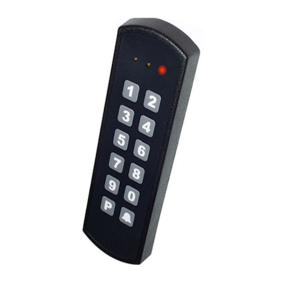
SA840-A30
INSTALLATIONS MANUAL
Rev. 4.00
KEYPAD / PROX COMBO
•
MULTI PROTOKOL OUTPUT
•
SUITS MOST CONTROL PANELS
•
ALSO FOR OUTDOOR USE
•
SKAFOR approved in class 3
•
This manual applies for serial no. greater than 1xx20000
SA840-A30 emulates ABA mag. reader, Wiegand reader, RS232 and RS485
SA840-A30 has a programmable facility code for Wiegand interface
SA840-A30 interfaces directly to Alphatronics, Cooper, Castle and others
SA840-A30 is a molded weatherproof construction for outdoor use
SA840-A30 has an optical tamper security circuit
SA840-A30 LED's and buzzer can be externally controlled
SA840-A30 has electrical isolated output for tamper/sabotage
SA840-A30 can be connected directly to PC or printer
SA840-A30 can be part of a SA850-series network
SA840-A30 uses standard 125KHz EM4100-based prox cords / tags
SA840-A30 is SKAFOR approved in class 3 (AIA 212.069)
Select output format
Output format selection is done during power-up.
Connect wires a shown in below table, apply power, wait for buzzer acknowledge
and finish by disconnection power and the wires from below table.
Wire connection for programming
YELW
GREEN to
VIOLET to
WHITE
nothing
nothing
YELLOW
GREEN to
VIOLET to
nothing
WHITE
nothing
YELLOW
GREEN to
VIOLET to
nothing
nothing
WHITE
YELLOW
GREEN to
VIOLET to
PINK
nothing
nothing
YELLOWl
GREEN to
VIOLET to
PINK+WHT
nothing
nothing
YELLOW
GREEN to
VIOLET to
PINK
WHITE
nothing
YELLOW
GREEN to
VIOLET to
PINK
nothing
WHITE
YELLOW
GREEN to
VIOLET to
nothing
PINK
nothing
YELLOW
GREEN to
VIOLET to
WHITE
PINK
nothing
YELLOW
GREEN to
VIOLET to
nothing
WHITE
GREEN
YELLOW
GREEN to
VIOLET to
nothing
PINK
WHITE
Programming sequence:
1.
Select output format and connect wires acordingly
2.
If protocol 6 then the tamper circuit can be disabled connecting the
BROWN wire to ground now.
3.
Connect power
4.
Potocol 6/8/10 (Red LED flashes): Enter ID 1-8 or hold a random
prox up to the reader and wait for number of beeps according to ID
no. If this is not done then ID=1 (Cooper) or ID=8 (AVNG).
5.
Await number of beeps according to format no.
6.
Disconnet power and wires.
SA840-A30 is now programmet and ready for use. Programming is stored in
internal non-volatile memory of SA840-A30. Fascility code, if needed, can be
changed by use of KeyLink+ TECH PC program. If programming sequence needs
changede then first follow below procedure for
Factory reset
1.
Disconnect power
2.
Connect PINK wire to ground (BLACK)
3.
Wait 5 seconds until red LED flashes
4.
Disconnect the PINK wire within next 5 seconds
5.
Disconnect power.
SA840 is now back in factory deafault state and a new protocol can be selected.
sa840_a30_inst_eng_400.doc
Format
Output format
no.
1
ABA (magstripe card)
Deafault selected
2
Wiegand
26-bit
3
RS232, 9600,N,8,1
Log function
4
MI Wiegand
(26/8-bit)
Like til Motorola/Indala
5
UT
For use with Unitek, NOX Syst.
6
AVNG
For AlphaVisionNG/CP-508LCD
7
ATS Wiegand
8
COOPER
For RS central panels
9
TAC Wiegand
For I/Net Seven
10
Castle
(ver 4 eller nyere)
For CS2600/2700/2800
11
TAC ABA
For til I/Net Seven
Factory reset
.
Mounting
SA840 mounts with only 2 screws on flat building surface
Connect SA840 wires appropriate and test tamper circuit with function 42 (
4
test)
. Tighten screws.
Clean key surface. Remove adhesive protection from front cover foil and place it
5
carefully on the SA850.
Red
8-24V DC
Back
Ground. 0V
Green/White
-
Green/Brown
-
Yellow
CLS (ABA), Data 0 (Wiegand)
Green
CCLK (ABA), Data 1 (Wiegand)
Violet
CDAT (ABA)
Blue
Tamper loop, wire 1
Blue/Pink
Tamper loop, wire 2
Gray/Pink
RS485 data, A (RS485)
Grey
RS485 data, B (RS485), TX (RS232)
White
LED indput
Pink
Buzzer input
Brown
Synchronizing. Only if two SA840's are placed closer than 50cm to each other.
Technical specifications
Power supply
Current consumption
Tamper loop
Output formats
RS232 (9600,N,8,1) , RS485, Wiegand, ABA,
Wiegand facility code
Network ID at delivery
Prox reading distance
Prox type
Dimensions (H-W-D)
0.59in-1.93in-0.59in (150mm-49mm-15mm)
Weight
Operating temperatures
Operating humidity
Wire
All specifications are subject to change. For latest info check on www.keyseven.com.
Having problems? Contact your dealer or visit our
homepage www.keyseven.com.
Mark the 4 drilling holes with the
1
Drill Guide and drill the holes
according to the wall material.
Fasten the nylon reflector.
2
Guide the cable trough the hole in
3
the wall and fasten screws loosely.
Sabotage
(open collector output)
(open collector output)
(open collector output)
8V to 24V DC
typical 80mA
isolated, max100mA, 25 ohm, 50V
UT, AVNG, TAC
Programmable, default 7
up to 10 cm.
125kHz, auto-tuning, EM4102 compatible
10.2oz (286g)
-30°F to 150°F (-35°C to 65°C)
0%-99%
10' (3 m), 14-lead
1
Advertisement
Table of Contents

Related Manuals for Key 7 SA840-A30

Summary of Contents for Key 7 SA840-A30
- Page 1 Await number of beeps according to format no. Disconnet power and wires. Having problems? Contact your dealer or visit our SA840-A30 is now programmet and ready for use. Programming is stored in homepage www.keyseven.com. internal non-volatile memory of SA840-A30. Fascility code, if needed, can be changed by use of KeyLink+ TECH PC program.
- Page 2 Drill guide...
Need help?
Do you have a question about the SA840-A30 and is the answer not in the manual?
Questions and answers