Table of Contents
Advertisement
Quick Links
Advertisement
Table of Contents

Related Manuals for ADB EURODIM TWIN TECH

Summary of Contents for ADB EURODIM TWIN TECH
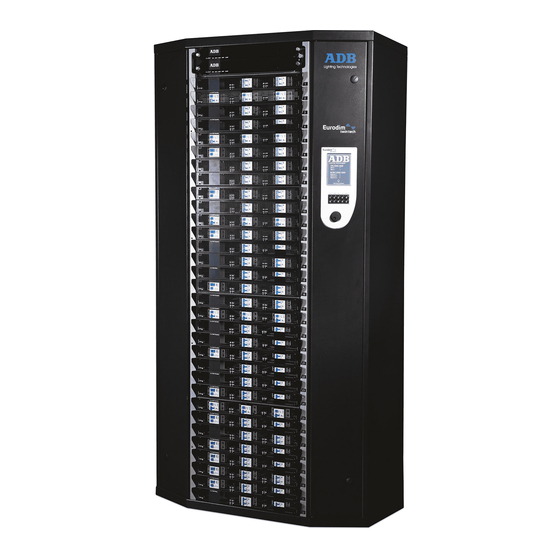
- Page 1 _____________ Eurodim Twintech Dimmer Cabinet _____________ User Manual V2.0...
-
Page 3: Table Of Contents
Presentation of the Home Page ....................... 18 Presentation of the Cabinet Diagnostic Page ................... 19 Controller (CTRL) Information....................... 20 EURODIM Twin Tech Information ....................20 DMX Information .......................... 21 Presentation of the ARTNET/sACN Information Page ..............23 Description of the Menus ........................ 24 Patch Menu ........................... - Page 4 EURODIM TWIN TECH 7.2.1 Range Key ..........................32 Power Configuration Menu ......................33 7.3.1 Module identification ....................... 34 7.3.2 COMPARE Key ........................... 35 REF. PRES. Key ........................35 7.3.3 7.3.4 Range Key ..........................36 Cues Menu ............................ 37 7.4.1 Cues Menu –...
- Page 5 Synchronisation Menu ........................83 Managing the Alarms ........................85 Errors List Screen Page........................86 8.1.1 List of Errors displayed in the EURODIM Twin Tech Frame ............86 8.1.2 List of Errors displayed in the CTRL Board Frame ..............87 8.1.3 List of Errors displayed in the Modules Frame .................
-
Page 6: Safety
Do not attempt installation unless you are suitably qualified. Installation errors may endanger operators and cause system damage and failure. If you do not understand a point in this manual, don’t guess. Contact ADB or one of our authorized distribution partners for advice. -
Page 7: Foreword
Important note: The present manual does not describe the functions relating to the ADB service menu. This menu is dedicated to qualified personnel trained by the hardware supplier, and to the ADB Stagelight technical department. -
Page 8: Description Of The Unit
EURODIM TWIN TECH 2.1 D ESCRIPTION OF THE user is provided with: 1 - A backlit LCD touch-screen enabling access to all menus 2 - A numeric keyboard 3 - A navigation/validation pushbutton - wheel When the right-hand side door of the cabinet is opened, the rear of the Unit gives access to the following:... - Page 9 EURODIM TWIN TECH 1 - An opening on the rear face to activate the software reset button (in the event that the touch screen becomes blocked) 2 - An opening in the side face for insertion of the SD memory card 3 - A connector to link up to the Twin Tech cabinet Controller units.
-
Page 10: Using The Ttd Human Interface (Hmi)
EURODIM TWIN TECH 2.2 U TTD HUMAN INTERFACE (HMI) SING THE 2.2.1 LCD Display When the cabinet is activated, an initial home page appears on the LCD display, allowing access to the “Cabinet diagnostic” screen page, which is considered as the main screen. -
Page 11: Accessing The Ttd Human Interface (Hmi)
EURODIM TWIN TECH − Cancel the validation of a field when the latter is edited. Pressing the navigation wheel enables the user to: − Edit a field to be filled in, − Validate the highlighted field, − Validate or cancel a function, −... -
Page 12: Screensaver
EURODIM TWIN TECH Level 0 does not allow access to any menu or function. Depending on the authorised access level, certain functions or menus remain blocked. Should you attempt to access these, the software will ask you to enter the access code for the next level in order to authorise access to the function or menu. -
Page 13: Menu Tree-Structure
EURODIM TWIN TECH 2.6 M TRUCTURE Cabinet Menu 1 Patch A & B Screensaver diagnostic Laws/M. Fact, Inrush, preheat Power Conf. Mem./DMX fail Edit cue Capture cue Play cue Copy cue Erase cue Prior/DMX fail Play chaser Settings Cont. Menu 2... - Page 14 EURODIM TWIN TECH Scan loads Learn Menu 2 Scan Mod. measurements mod. Mod. Diag. Artnet or sACN Patch See Artnet, sACN, or IP config Artnet, sACN and IP config ADB Service (functions not described) Synchronisation Page 12 sur 92...
-
Page 15: Cabinet Configuration
EURODIM TWIN TECH ABINET ONFIGURATION The upper part of the Twin Tech cabinet may be equipped with: − Two Controller units, − or a Controller unit and a backup power supply module. The Controller units, control all of the circuits (128 max.) constituting the modules available in the cabinet (32 max.), according to the configuration recorded by the Unit software (patch) and the channel values... -
Page 16: Module Control
EURODIM TWIN TECH If one controller is functional and inserted into the slot at the bottom, the cabinet will work but the human interface will not be able to present the modules or diagnostic information modules 3.2 M ODULE ONTROL The selector allows the Controller unit in service to be chosen. -
Page 17: Cabinet Ventilation
EURODIM TWIN TECH Notes: The PCB3031 board also enables: − the DMX A inputs to be connected between controllers (SW1, selectors 5 and 6 set to ON) − the DMX B inputs to be connected between controllers (SW1, selectors 7 and 8 set to ON) PCB 3031 board 3.3 C... -
Page 18: Description Of The Laws And Modes
EURODIM TWIN TECH The user must then: − Define or validate the control of each module’s circuits by allocating the DMX channels. See Patch, ARTNET/sACN Patch and ARTNET/sACN Configuration menus. − Define the laws or mode and multiplying factor applicable on each of the circuits constituting a module with respect to the loads that are wired at each circuit’s output. - Page 19 EURODIM TWIN TECH For all other laws, the circuit uses a filtering characterised by a 400 µS rise time. The rise time is 400 µS by default. Law curve giving the relationship between the DMX input (0 to 255) of the function law and the output after application of the law in the same units.
-
Page 20: Presentation Of The Home Page
EURODIM TWIN TECH RESENTATION OF THE This screen page is displayed as soon as the cabinet is switched on. It gives the information concerning the name of the cabinet, the config (show played), the User identification, the start addresses for the DMX A... -
Page 21: Presentation Of The Cabinet Diagnostic Page
EURODIM TWIN TECH RESENTATION OF THE ABINET IAGNOSTIC This screen shows the cabinet diagnostic information. This page is divided into four zones: − A zone on the top provide the name of the cabinet, and the name of the configuration (played show). -
Page 22: Controller (Ctrl) Information
EURODIM TWIN TECH 5.1 C (CTRL) I ONTROLLER NFORMATION Note: The information is present if the controller is physically connected and operational in the cabinet. − CTRL board active: • "Yes" if the controller is selected by the cabinet controller selector (position 1 for controller 1 and position 2 for controller 2 or A/R for both), •... -
Page 23: Dmx Information
EURODIM TWIN TECH When any problem is detected by the cabinet. An exclamation mark then appears to the right of the screen page. In this case, press the exclamation mark to display a screen page, "Error list". When you press the exclamation mark then appears the Error list. - Page 24 EURODIM TWIN TECH − DMX A/B present: Yes; • Yes: DMX signal reception detected • No: DMX signal reception missing. − Patch A/B (see "PATCH" menu): • Yes: the addressing filled-in in each patch at the circuits is not in ascending order, •...
-
Page 25: Presentation Of The Artnet/Sacn Information Page
EURODIM TWIN TECH ARTNET/ ACN I RESENTATION OF THE NFORMATION Explanation of the fields: see chapter: "ENET INFO". Page 23 sur 92... -
Page 26: Description Of The Menus
EURODIM TWIN TECH ESCRIPTION OF THE ENUS Page 1 Page 2 Two screen pages are available in order to choose a function, enabling the cabinet to be configured using one of the following menus: − DMX PATCH: to edit patch A or B for each circuit −... -
Page 27: Patch Menu
ENET INFO: general information on the ARTNET/sACN universes and the Ethernet connection − ENET SET.: to configure the three ARTNET/sACN universes, the IP address and the RDM. − SERVICE: function available to ADB technical service only − SYNCHRO: to synchronise the parameters recorded between each of the controllers Note: All the information displayed in the different menus originates from controller 1 if two controllers are present in the cabinet. - Page 28 EURODIM TWIN TECH Module reference channel Page patch A Module reference channel Page patch B Page 26 sur 92...
- Page 29 EURODIM TWIN TECH Reminder The referencing of the modules in the cabinet starts at 1 in relation to the first location located at the top of the cabinet, up to 32. The left-hand column contains the referencing of the modules and circuits present in the cabinet.
-
Page 30: Range Key
EURODIM TWIN TECH 7.1.1 Range Key Used to attribute an ascending patch value in graduations of 1 to a set of circuits, included within one section. Enter: − The start dimmer number (From dim), − The end dimmer number (To dim), −... -
Page 31: A ═> B Key
EURODIM TWIN TECH A ═> B Key 7.1.2 Used to copy all of the values from patch A to patch B and make them identical 7.2 L ULTIPLYING ACTOR LASH AND REHEAT This function is used to attribute a law, a multiplying factor, a speed of flash or a level of preheat to a circuit or set of circuits. - Page 32 EURODIM TWIN TECH Push to a circuit on the column curves to choose the right curve: Reminder The left-hand column contains the referencing of the modules and circuits present in the cabinet: − Example: Value 1/1: references module 1/circuit 1 of the module −...
- Page 33 EURODIM TWIN TECH Example of a circuit’s output voltage: Entry DMX channel value (50%) 120 V law Mult. fact.: 50% 230 V 115 V 57 V 29 V Use the wheel in order to rapidly move to the row of a circuit. The row selected is highlighted.
-
Page 34: Range Key
EURODIM TWIN TECH 7.2.1 Range Key Used to attribute the same law and the same multiplying factor to a set of circuits, included within a range. Range key page Enter: − The start dimmer number (From dim), − The end dimmer number (To dim), −... -
Page 35: Power Configuration Menu
This function configures the module type depending on its position in the cabinet. Normally, the use of this tools is only necessary for the initial setup of the cabinet. This tool is protected by level 4 password (ADB password). Power page... -
Page 36: Module Identification
3R (3 individual protections) 4R (4 individual protections) EURODIM TWIN TECH module identification table In the Reference column, we are given the type of module that will actually be used by the controller to control the circuits. This reference may be modified manually. If a position in the cabinet is not used, the user must fill it in as an "undefined slot". -
Page 37: Compare Key
EURODIM TWIN TECH 7.3.2 COMPARE Key This function is used to compare the ID given in the PRESENT column and the ID given in the REFERENCE column, for each module. This is used to check that the content of the references is up-to-date with respect to the modules actually installed. -
Page 38: Range Key
EURODIM TWIN TECH 7.3.4 Range Key Used to attribute the same ID to a set of modules, included within a range. Range key page Enter: − The start module number, − The end module number, − The ID to be attributed to these modules, −... -
Page 39: Cues Menu
EURODIM TWIN TECH 7.4 C 80 cues + 1 emergency cue (cue no. 0) are available to record pre-defined circuit-control values. These cues can be played. A special (emergency) cue bearing the no. 0 is available to replace the circuit-control values in the event that the DMX and/or ARTNET signals is not present. -
Page 40: Cues Menu - Edit
EURODIM TWIN TECH − Cue - Erase: Erase a cue’s content − Cue - PRIOR. DMX FAIL: Select a source to replace an absence of DMX/ARTNET/sACN − Chaser - Play all existing cues on loop − 7.4.1 Cues Menu – Edit This function is used to fill in the content of the 80 cues + cue 0. - Page 41 EURODIM TWIN TECH To edit the cue number: − Touch the screen or use the wheel to select the zone of the number in question, − Type the number using the keyboard, − Confirm the cue to be edited by touching the zone, or use the wheel.
- Page 42 EURODIM TWIN TECH Enter: − The start dimmer number (From dim), − The end dimmer number (To dim), − The intensity to be attributed to these circuits, − Confirm with the OK button Note: the circuit's first number ("From dim") must be < the circuit’s second number ("To dim") during definition of the range.
-
Page 43: Cues Menu - Capture
EURODIM TWIN TECH Enter: − The fade time (minutes, seconds), − The wait time (minutes, seconds), − The existence of the cue (select yes/no), − Confirm with the OK button. Note: the maximum time taken into account for the minutes is limited to 99 minutes. - Page 44 EURODIM TWIN TECH Selecting a cue To select a cue, go to the cue number (highlighted), either by touching the screen or using the wheel. To edit the cue number: − Touch the screen or use the wheel to select the zone of the number in question, −...
-
Page 45: Cues Menu - Play
EURODIM TWIN TECH values are displayed. Press the "SAVE" key to save the intensities in the cue displayed. The cue becomes existing ("E"). 7.4.3 Cues Menu – Play This function is used to play an existing cue. The fade time corresponds to the rise time defined in the "Cue–Edit" menu. - Page 46 EURODIM TWIN TECH Otherwise, press keyboard key 1 to scan the cues in ascending order, or press keyboard key 0 to scan the cues in descending order. Play a cue Press the "Play" key to launch the cue. The information in this status lets you know the progress of memory fade: −...
-
Page 47: Cues Menu - Copy
EURODIM TWIN TECH 7.4.4 Cues Menu – Copy This function is used to copy an existing cue to any other cue (existing or not). Existing source cue destination cue indication Selecting the original cue The field memory source can only display existing memories. -
Page 48: Cues Menu - Erase
EURODIM TWIN TECH Selecting the destination cue Each of the cues may be overwritten. To select a cue, position on the cue number (highlighted), either by touching the screen or using the wheel. To edit the cue number: − Touch the screen or use the wheel to select the zone of the number in question, −... - Page 49 EURODIM TWIN TECH Selecting a cue Only the existing cues will be displayed. Note: Cue 0 always exists. To select a cue, go to the cue number (highlighted), either by touching the screen or using the wheel. To edit the cue number: −...
-
Page 50: Cues Menu - Priority/Dmx Fail
EURODIM TWIN TECH 7.4.6 Cues Menu - Priority/DMX fail This function is used to prioritise the selection amongst the DMX/ARTNET/sACN inputs and cue played, and also to replace a missing source. Priority to the highest DMX/ARTNET/sACN value values are no longer... -
Page 51: Cues Menu - Play Chaser
EURODIM TWIN TECH − Control by cue 0 with fade (rise time of cue 0), − 0% control (black) with fade in five seconds. Select one of the possibilities by touching one of the keys. You can change the time before the source is replaced. Push the delay key. - Page 52 EURODIM TWIN TECH The list of cues played is displayed in the window. Press the "PLAY" key to launch the chaser. The cues are played in ascending order. Press the "Stop" key to interrupt the chaser. The DMX/ARTNET signals once more control the circuits.
-
Page 53: Search
EURODIM TWIN TECH 7.5 S EARCH This function displays all parameters in modules Parameters displayed are: • Power info: the type of module used by the controllers. • Circuit qty.: Number of circuit in the module. • Circuit: position of the circuit taking into account the number of circuit in the previous modules. - Page 54 EURODIM TWIN TECH Note: If a module contains less than four circuits, the circuits will be displayed with empty "------" to indicate that there is not physically present in the circuit module. Selection of modules and outputs. To select a module or an output, position the cursor on the number of the module or the output (highlighted), either by touchscreen or use of the dial.
-
Page 55: Test And Flash Menu
EURODIM TWIN TECH 7.6 T EST AND LASH This menu is used to test the outputs of each circuit via a command from controller 1 or 2. Output/patch relationship In order to be able to control a circuit (output) or a set of circuits with respect to controller 1 or 2 (if present), verify the position of the cabinet selector in order to ensure that it matches the control by the controller selected on the screen. -
Page 56: Flash Tab
EURODIM TWIN TECH To select an output, position on the output number (highlighted), either by touching the screen or using the wheel. To edit the output number: − Touch the screen to select the output number or use the wheel, −... -
Page 57: Load/Save Menu
EURODIM TWIN TECH According to the output function selected, the - value of corresponding patches A and B is displayed. Adjust, in the same manner: − the output control intensity, value row, intensity between 0 and 100% (FF) − the output control duration, delay row, duration between 0 ( ~ 0.5 secs) and 60 secs Touch the screen or use the wheel to select either the manual or automated test. -
Page 58: Saving The Parameters
EURODIM TWIN TECH In order to conduct a save (backup) or load operation, the SD card must be present in the slot planned in the TTD HUMAN INTERFACE (HMI) Unit, located behind the right contractors door. If no card is detected, the status row displays "No card detected". -
Page 59: Loading The Parameters
EURODIM TWIN TECH Touch the "SAVE" key to launch the save. A first window requests the save date to be manually recorded. After validation, a second window requests confirmation of the save cue execution (yes/no). Next, a third window requests the user’s confirmation of the save operation configured as described. -
Page 60: Load Scanning Menu
EURODIM TWIN TECH Touch to select the settings: − Buzzer: When it is activated ("ON"), the little buzzer emits the signal when there has been action on the wheel, the numeric touchpad or the touch-screen, − Language: French/English, − Screensaver: If the screensaver is active ("ON"), the TTD HUMAN INTERFACE (HMI) returns to the home page if there has not been any action by the user and resets the user level to zero. - Page 61 EURODIM TWIN TECH This function is used to scan the loads present at the output of each circuit and check that the loads have not changed with respect to a previous state. This verification is performed in two stages: −...
-
Page 62: Load Scanning Menu - Learn
EURODIM TWIN TECH 7.9.1 Load Scanning Menu – Learn Important: This function can only be used if the sequential diagnostic kit has been installed in the cabinet, it being used to measure the neutral current on the module power line (busbar). - Page 63 EURODIM TWIN TECH To edit and select a load: − Touch the screen to select the row or use the dial, − A table featuring all the available loads is displayed, − Select a load value present in the table, either by touching the screen or using the wheel, −...
-
Page 64: Range Key
EURODIM TWIN TECH 7.9.3 Range Key Used to attribute the same load value to a set of circuits, included within a range. Enter: − The start dimmer number (From dim), − The end dimmer number (To dim), − The load to be attributed to these circuits (a table appears enabling the load to be selected, see manual load selection), −... -
Page 65: Automatically Selecting The Loads
EURODIM TWIN TECH 7.9.4 Automatically selecting the loads Press the "AUTOMATIC" key; three options are available: − Measurement: the load information available in the "Measurement" column of all the circuits is recopied to the "EDIT” column. After copying, the name of the left-hand column changes and becomes "SCANNED",... -
Page 66: Loads Scanning Menu - Scan
EURODIM TWIN TECH 7.9.5 Loads Scanning Menu - Scan Important: this function works if the sequential diagnostic kit has been installed in the cabinet. In effect, it is used to measure the neutral current on the module power line (busbar). -
Page 67: Range Key
EURODIM TWIN TECH A circuit cannot be selected if it is defined as "Non dim" (see information in Status) because in this case, this type of module does not enable dimming 7.9.6 Range Key Used to select a set of circuits to be scanned, included within a range. -
Page 68: Scanning The Outputs
EURODIM TWIN TECH 7.9.7 Scanning the Outputs Launch the scan by pressing the "SCAN" key. Confirm your choice. Several stages are conducted during the scan of a circuit’s output and which can be viewed on the status row: − Test at 14% (of 230V) in order to detect the presence of a short circuit (Stopping of the procedure in the event of a short-circuit). -
Page 69: Module Measurements Menu
EURODIM TWIN TECH 7.10 M ODULE EASUREMENTS This function displays the values measured for the sinewave and thyristor modules with a full-diagnostic option Only the sinewave or Dimswitch/fluo modules with full-diagnostic option can give measurements or diagnostic. The fluo and Dimswitch modules without this diagnosis will always give N/A (not available). -
Page 70: Selecting The Modules And Circuits
EURODIM TWIN TECH 7.10.1 Selecting the modules and circuits To select a module or circuit, position on the module or dimmer number (highlighted), either by touching the screen or using the wheel. To display the module or circuit measurements: −... -
Page 71: Selecting The Modules And Circuits
EURODIM TWIN TECH 7.11.1 Selecting the modules and circuits To select a module or circuit, position on the module or dimmer number (highlighted), either by touching the screen or using the wheel. To display the module or circuit measurements: −... - Page 72 EURODIM TWIN TECH Thyristor (per circuit): 1 - Displays "OK" if the breaker is engaged 2 - Displays "TRIPPED" if the breaker has blown Load (per circuit) Sinewave & Thyristor with diag: 1 - Displays "N/A": • The control is set to zero •...
- Page 73 EURODIM TWIN TECH • if the load > 5.5.5KW (for a 5kW module) • if the load is > 11KW (for a 10kW module) 3 - Displays "NO" in all other cases OverCurrent Sinewave: • (per circuit) Displays “low”: if the current is > 13 A •...
- Page 74 EURODIM TWIN TECH Note: If the main voltage < 205 V, the sinewave module no longer controls its circuits Thyristor: always N/A Controller vers. Module software version Sec. vers. Controller Indication available only for sinewave modules Page 72 sur 92...
-
Page 75: Enet Patch Menu
EURODIM TWIN TECH 7.12 ENET P ATCH This function is used to configure a patch on a circuit or a set of circuits for each of universes 1, 2 and 3. This configuration is used to attribute the value of a channel of each universe to the control of a circuit of the cabinet. - Page 76 EURODIM TWIN TECH Reminder The referencing of the modules in the cabinet starts at 1 in relation to the first location situated at the top of the cabinet, up to 32. The left-hand column contains the referencing of the modules and circuits present in the cabinet: −...
-
Page 77: Range Key
EURODIM TWIN TECH − The Range key in order to enter values between two circuit references. Important: Specific case for row 1/1: If key 0 or 1 is used, the value taken into consideration corresponds to the content of output 128 if available, otherwise to output 127, and so on. -
Page 78: Enet Info Menu
EURODIM TWIN TECH − The start channel value to be taken into consideration for the increment in steps of 1 − Confirm with the OK button. Note: the circuit's first number ("From dim") must be < the circuit’s second number ("To dim") during definition of the range. -
Page 79: Artnet Information
EURODIM TWIN TECH This page is divided into two zones: − A zone (CTRL1 or CRTL2 key) providing information on the status of the universes and their configurations for each controller, − A zone (ENET) providing the IP addresses, the Mask and the Broadcast addresses entered for each controller (to change the displayed information, press the box). - Page 80 Subnet: value between 0 and 15, see "ENET SET" menu − Port: value between 0 and 15, see "ENET SET" menu Note: When the ARTNET entries are controlled by an ISIS rotating ADB console, all the subnets must have the same number. Ethernet Information The IP address of each controller and the value of the sub-network mask are given.
-
Page 81: Sacn Information
EURODIM TWIN TECH 7.13.2 sACN Information For each of the three universes (1, 2, 3, change the information with the arrow key), the following information is available: − Mode: Not used or ARNET or sACN (see "ENET SET" menu) −... -
Page 82: Enet Set Menu
EURODIM TWIN TECH − SCR Name: name of the emitter of sACN − Scr IP addr: Adress IP of the emitter of sACN − Scr priority: Priority of the emitter (Value between 0 and 200) Ethernet Information The IP address of each controller and the value of the sub-network mask are given. -
Page 83: Selecting Universe Mode
EURODIM TWIN TECH 7.14.1 Selecting Universe Mode For each universe, choose the operating mode: − “OFF” mode: the universe is not taken into consideration for the control of the circuits, − “ARTNET” mode: the Arnet universe is taken into consideration for the control of the circuits. -
Page 84: Ip Configuration
EURODIM TWIN TECH 7.14.3 IP configuration: You can change the IP address and Mask for each controller. Position on the IP address or Mask value, either by touching the screen or using the wheel. The value is highlighted. − Type the value using the keyboard, −... -
Page 85: Rdm Setting
EURODIM TWIN TECH 7.14.4 RDM setting: You can validate the RDM ON or OFF. Be careful, RDM is mandatory to use the RDM Dimmer manager software. 7.15 S YNCHRONISATION This function is used to perform a copy operation between the controllers in the event that a new CTRL (blank or containing old data) is put in place in the cabinet. - Page 86 EURODIM TWIN TECH - Modules used, - Cue priority, - ARTNET and sACN configuration, - Load measurements, - Action in the event of an absent source. Touch one of the "SYNC" keys to launch the copy procedure between controllers, that is, from controller 1 to controller 2 or vice versa.
-
Page 87: Managing The Alarms
EURODIM TWIN TECH ANAGING THE LARMS The cabinet diagnostic page indicates any malfunctions of the cabinet with a warning message. Example: "Choose the modules to be used". An exclamation mark also appears. Touch the exclamation mark to display a screen page, grouping together the errors list. -
Page 88: Errors List Screen Page
Touch one of the two keys to display the error messages. 8.1.1 List of Errors displayed in the EURODIM Twin Tech Frame 1 - Displays an error on a mains phase: example: "phase r error". Explanation: the voltage measured at the controller input is outside the operation range. -
Page 89: List Of Errors Displayed In The Ctrl Board Frame
EURODIM TWIN TECH 8.1.2 List of Errors displayed in the CTRL Board Frame 1 - “CTRL error”: explanation: there are three processors in each controller. Processor 2 or 3 is not responding. In this case, no dimming will be possible on this controller. - Page 90 EURODIM TWIN TECH For more information, press the MOD DIAG button that appears next to the error. This provides a shortcut to the MOD. DIAG. menu of the module of the first circuit experiencing an error. Directly displays the first circuit where an error has been detected. Verify on which circuit row the error appears.
-
Page 91: Fault-Clearing Guide
EURODIM TWIN TECH AULT LEARING UIDE Each controller is equipped with several LEDs for visual monitoring the information available on the interface. Light State Operation Action RUN light (green) Flashes RUN light (green) Solid or off Controller operating error (crashing) -
Page 92: Procedure To Be Followed In The Event Of An Error
EURODIM TWIN TECH 9.1 P ROCEDURE TO BE FOLLOWED IN THE VENT OF AN RROR Errors list Action Downgraded mode − Verify the external network r, s, t phase error The modules connected on the faulty phase are no − Verify the connections on the longer useable. - Page 93 Frequency error Poor circuit control (outputs flash) the cabinet’s input − Verify the operating frequency selected in the software (ADB service menu) − Change the faulty CTRL or reload Software version error the software from the TTD HUMAN INTERFACE (HMI) (ADB...
- Page 94 EURODIM TWIN TECH Notes: Page 92 sur 92...
- Page 96 Headquarters & International Sales CLAY PAKY S.p.A. Via Pastrengo, 3/b - 24068 Seriate (BG) ITALY Contact: info@adblighting.com Phone: +39.035.654.311 Fax: +39.035.30.18.76 info@claypaky.it www.claypaky.com...
Need help?
Do you have a question about the EURODIM TWIN TECH and is the answer not in the manual?
Questions and answers