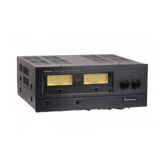
Hitachi HMA-8300 Service Manual
High efficiency high power audio amplifier
Hide thumbs
Also See for HMA-8300:
- Service manual (25 pages) ,
- Instruction manual (20 pages) ,
- Service manual (20 pages)
Table of Contents
Advertisement
Quick Links
SERVICE MANUAL
i
SPECIFICATIONS
Circuitry
Peak RMS power (Music power)
Continuous RMS power output
Harmonic distortion
(at rated output)
(at 100 W output)
(at 1 W output)
Power bandwidth (IHF)
Frequency characteristics
Input sensitivity
Damping factor
Channel separation
Signal-to-noise ratio
(IHF, A network)
Speaker impedance
Semi-conductors
Power supply
Power consumption
Dimensions
Weight
Specifications and designs may be changed without notice for improvement.
STEREO POWER AMPLIFIER
English
Deutsch
Français
A Newly Developed High Efficiency High Power Audio Amplifier
(Named series E Amplifier)
400 W/ch + 400 W/ch (8 ohms)
200 watts per channel min. RMS,
at 8 ohms from 20 Hz to 20 kHz,
with no more than 0.1% total harmonic distortion
200 W/ch + 200 W/ch (4 ohms, 1 kHz, T.H.D. 0.1%)
Less than 0.1%
Less than 0.05%
Less than 0.05%
5 Hz - 30 kHz (8 ohms)
5 Hz -80 kHz (t? dB)
1 V (50 k ohms)
50 (20 Hz — 20 kHz, 8 ohms)
100 (1 kHz, 8 ohms)
80 dB (1 kHz, 8 ohms)
110 dB
4 - 1 6 ohms (except for Switzerland, U.K. & Sweden)
8 — 1 6 ohms (for Switzerland, U.K. & Sweden)
2 ICs, 40 transistors and 51 diodes
AC 120 V, -220 - 240 V, 50/60 Hz
850 W or 1020 VA (AC 120 V)
1470 W (-220-240 V, 4 ohms)
1100 W (- 220 - 240 V. 8 ohms)
435 (W)
182 (H) x 404 (D) mm
X
17-1/8 (W) x 7-3/16 (H) x 16 (D) in.
24 kg
53 lbs.
June1977
NO. 117
For original manual click
here
Advertisement
Table of Contents

Related Manuals for Hitachi HMA-8300


Summary of Contents for Hitachi HMA-8300
- Page 1 English NO. 117 SERVICE MANUAL Deutsch Français SPECIFICATIONS Circuitry A Newly Developed High Efficiency High Power Audio Amplifier (Named series E Amplifier) 400 W/ch + 400 W/ch (8 ohms) Peak RMS power (Music power) Continuous RMS power output 200 watts per channel min. RMS, at 8 ohms from 20 Hz to 20 kHz, with no more than 0.1% total harmonic distortion 200 W/ch + 200 W/ch (4 ohms, 1 kHz, T.H.D.
-
Page 2: Technische Daten
TECHNISCHE DATEN Schaltung Neuentwickelter Hochleistungs-Endverstärker Spitzen-RMS-Leistung 400 W/K. + 400 W/K. (8 Ohm) (Musikleistung) Dauer-R MS-Leistung 200 W/K. + 200 W/K. (8 Ohm, 20 Hz - 20 kHz, 0,1% Gesamtklirrfaktor) 200 W/K. + 200 W/K. (4 Ohm, 1 kHz, 0,1% Gesamtklirrfaktor) Klirrfaktor (bei Nennleistung) Weniger als 0,1%... - Page 3 DISASSEMBLY AND REPLACEMENT • ZERLEGUNG UND AUSTAUSCH • DEMONTAGE ET REMONTAGE • Removing the upper cover, side cover, front panel & bottom plate • Ausbau der oberen Abdeckung, der Seitenwand, der Fronttafel und der Bodenplatte • Déposer le couvercle supérieur, le couvercle latéral, la facade et la plaque inférieure Upper cover Obere Abdeckung Couvercle supérieur...
- Page 4 • Removing the printed wiring board of the Audio, Meter • Ausbau der Leiterplatte des Verstärkers und des Anzeigeinstrumentes • Retirer la plaquette à circuit imprimé audio et de compteur Meter P.W.B. Anzeigeinstrument P.W.B. Compteur P.W.B. Fig. 4 Abb. 4 •...
- Page 5 berührt werden, wenn dieser für die Messung des Blind zu vermeiden. Beim Anschluß daher unbedingt darauf achten, daß die Farben und Kennzeichnungen überein stromes angeschlossen wird, da es ansonsten zu Störungen stimmen. kommen könnte. Den Gleichspannungsmesser vorsichtig behandeln. Isolationsband gegebenenfrUs um den Schra •...
- Page 6 (2) Meter sensitivity adjustment Adjust the sensitivity of the meter after the zero adjust ment is completed. Carry out the above with no load on the speaker terminals (speaker not connected). Connect an audio oscillator to the input terminals (IN PUT) and apply a 1kHz input signal.
- Page 7 DESCRIPTION OF THE NEW CIRCUIT out the push-pull operation and can drive the output 1. Dynaharmony (Series E Amplifier) output circuit stage with low distortion. The level of the music source changes momentarily, the percentage of high level (over 1/2 of peak value) is very 3.
- Page 8 5. Protection circuits 6. Meter circuit (1) Muting circuit This meter circuit contains the logarithmic-compression circuit. Fig. 13 shows the meter circuit in this set. R401, This set contains the muting circuit which cuts off CR401 and CR402 make the input signal logarithmic- the relay approx.
- Page 9 Transfer characteristics of diode CR402 Kennlinien der Diode CR402 Caractéristiques de transfert de diode CR402 Fig. 12 Abb. 12 Output signal waveform Ausgangssignal Forme d'onde de signal de sortie Input signal waveform (sine wave) Fig. 13 Eingangssignal (Sinus) Forme d'onde du signal d'entrée Abb.
- Page 10 BESCHREIBUNG DES NEUEN SCHALTKREISES 1. Dynaharmony-Ausgangsstufe (Serie E Verstärker) Der Kollektorstrom von Q703 beträgt daher: Der Pegel eines Musikstückes ändert ständig, wobei jedoch hochpegelige Signale (mehr als 1/2 des Spitzen wertes) nur sehr selten Vorkommen und nur etwa 2% der gesamten Musiksignale ausmachen.
- Page 11 PRINTED WIRING BOARD • PRINTPLATTEN • PLAN DE BASE METER PRINTED WIRING BOARD The terminal No. shows the stamp on the printed wiring board This number matches the number in the circuit diagram. The circuit symbol HBBh- means a fuse resistor. AUDIO PRINTED WIRING BOARD When replacing it with new one, refer to the CAUTION on page 13.
- Page 12 BLOCK DIAGRAM • BLOCKSCHEMA • SCHEMA...
-
Page 13: Circuit Diagram
Fuse resistors are used to improve safety (to prot CIRCUIT DIAGRAM When replacing them with new ones, be sure to u; type. Always use the designated fuse without fail. The circuit diagram is subject to change for improvement without notice... - Page 14 CH A RACTERISTI ifety (to protect the circuit). , be sure to use the designated out fail. Measuring Equipment--------------- Audio Osc. : MODEL 4494A AC Voltmeter : MODEL 3400A Distortion Meter : MODEL 4333A Meßgeräte Tonfrequenzgenerator : Modell 4494A Wechselstrom-Vollmeter : Modell 3400A K h rr faktor me sser : Modell 4333A Equipement de mesure Générateur à...
- Page 15 Wenn die Netzspannung zunimmt, erhöht sich die Tem den Ausgangsklemmen durch eine Filterschaltung auf peratur aufgrund der größeren Leistungsaufnahme der gespürt, die aus den Teilen R503 und C501 gebildet Transistoren, so daß die Spannung zwischen der Basis wird. Wenn diese Gleichspannung positiv (+) ist, wird und dem Emitter verringert wird, wodurch der Blind...
- Page 16 RENSEIGNEMENTS CONCERNANT LE NOUVEAU CIRCUIT 1. Circuit de sortie dynaharmonique (Amplificateur ant collecteur de Q703 est comme suit: classe E) Le niveau du message sonore change momentanément, le pourcentage de signaux à haut niveau (plus de 1/2 de valeur de crête) est très faible, il est seulement inférieur de 2% du total des signaux du message musical.
- Page 17 Par ailleurs, quand la tension d'alimentation augmente, (3) Circuit de détection de tension à courant continu la production de chaleur de chaque semi-conducteur a (protection de haut-parleur) lieu à la suite de l’augmentation de la consommation Quand une tension à courant continu apparaît aux électrique, la tension entre la base et l'émetteur diminue bornes de haut-parleur quand le fonctionnement est et le courant déwatté...
-
Page 18: Troubleshooting
CHECKING THE OPERATION OF THE PROTECTION CIRCUIT 2.0peration check of the speaker protection circuit When the output circuit is repaired by replacing the power transistors, etc., perform an operation check on Make sure that the relay operates (a click sound is the ASO (Area of Safe Operation) detection circuit and heard) approx. -
Page 19: Fehlersuche
KONTROLLE DER FUNKTION DER SCHUTZSCHALTUNG Falls die Ausgangsschaltung repariert wurde, indem z.b. 30 Sekunden wieder einschalten. Wenn nun ein Aus die Leistungstransistoren usw. erneuert wurden, dann gangssignal an den Lautsprecherklemmen festgestellt muß die ASO-Schutzschaltung (ASO = Area of Safe Op wird bedeutet dies, daß... -
Page 20: Detection De Pannes
CONTRÔLE DE FONCTIONNEMENT DU CIRCUIT DE PROTECTION Quand le circuit de sortie est réparé à la suite du rem bornes de haut-parleur, c’est le signe que le circuit placement des transistors de puissance, etc, effectuer de détection de type ASO fonctionne normalement. vérification fonctionnement circuit... - Page 21 REPLACEMENT PARTS LIST • ERSATZTEILLISTE • TABLEAU DES PIECE Fuse resistors in this list are maked *. SYMBOL STOCK STOCK SYMBOL DESCRIPTION DESCRIPTION CAPACITORS Ceramic, discal 0.01/iF ±20% 500V C801 0245408 0252541 Electrolytic IOOO C802 for METER PRINTED WIRING BOARD for REAR PLATE ASSEMBLY 10/iF C401L,R...
- Page 22 SYMBOL STOCK SYMBOL STOCK DESCRIPTION DESCRIPTION R708L,R 0114171 Carbon film 2.7kft ±5% SRDViP Q712L,R 2328182 2SB608 R709L,R 0114169 Carbon film 2.2kft ±5% SRDViP Q713L,R 2328122 2SB628 ® R710L.R 0110621 Metal 10017 ±5% RN»/ R711L,R 0110621 Metal lOOft ±5% RN&B for DIAL MECHANISM ASSEMBLY R712L,R 0119445 Metal, oxide...
- Page 23 SYMBOL STOCK SYMBOL STOCK DESCRIPTION DESCRIPTION 2727181 Holder-fuse holder 300S7-(B) (for idle current adj.) VR701L.R 0151301 (for U.K., France, West Germany Australia) & for MECHANICAL PLATE ASSEMBLY 2667365 5P miniature connector (for power supply) 2667366 5P miniature connector (for power supply) 0156565 100kn-(B) (for input level adj.) 2667343...
- Page 24 4. Un filtre subsonique qui élimine les sons de très tant une grande puissance dynamique Head Office 5 - 1 , 1 -chôme, Marunouchi, Chiyoda-ku, Tokyo ^ Hitachi, Ltd. Tokyo Japan Tokyo (212) 1 1 1 1 ( 8 0 lines) Tel.
Need help?
Do you have a question about the HMA-8300 and is the answer not in the manual?
Questions and answers