Table of Contents
Advertisement
Quick Links
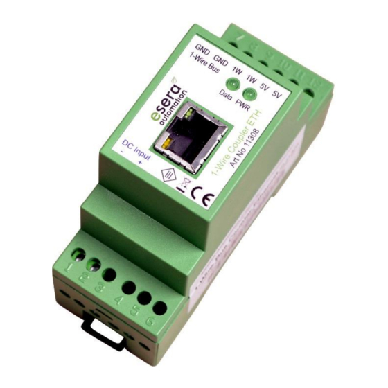
Art. No. 11308
Configuration:
•
Ethernet connection for 1-Wire bus
•
Galvanic separation of 1-Wire network
and computer
•
LED display for power, 1-Wire activity, link
and data transfer
•
Top-hat rail case for the assembly of the switchboard
•
Integrated power adapter for the voltage supply
of the 1-Wire bus
•
Wide voltage supply range
•
Connection for 1-Wire bus via screw terminals
•
Easy software-based integration as COM port
•
Low space requirement in the switchboard
•
Easy to assemble
1
Introduction
Before you start assembling the 1 Wire Bus Coupler Ethernet and before you take the device into operation,
please read these assembly and operating instructions carefully to the end, especially the section referring to the
safety notes.
2
Product description
The 1-Wire Bus Coupler Ethernet enables a stable and electrically isolated connection of the 1-Wire network to a
PC or minicomputer (e.g. Raspberry Pi). Ground loops or fault transmissions between 1-Wire network and
computer are prevented by the use of the 1-Wire bus coupler Ethernet.
Within the 1-Wire Bus Coupler, the serial to 1-Wire module DS2480 from Dallas / Maxim is used. This module - in
combination with the complex internal power supply and the Ethernet module - are the basis for a very stable 1-
Wire network.
The 1-wire master within the 1-wire bus coupler Ethernet (DS2480 module) supports the "Strong Pull Up" function
and is therefore particularly suitable for the operation of large 1-wire networks.
To configure the Ethernet interface, a suitable program "Config Tool" is available via the article download. The
"Config Tool" is part of the "Software package", which you will find in the article Download.
On computer side, the 1-Wire bus coupler is connected via a "Virtual Serial Port" (VSP). The "VSP_INSTALLER"
tool is available for configuring the VSP. Both programs are available for download in our webshop.
On software side, a serial interface (COM port) is available for integration into your application after installation of
the VSP.
An external power supply is required to operate the 1-wire Bus Coupler Ethernet module. The outputs of the
module (5V and 1-wire bus) are short-circuit-proof and galvanically connected to the supply voltage input. For
details on the connection, please refer to the "connection plan".
The 1-Wire Bus Coupler has LED displays for "Power" and "1-Wire activity", "Ethernet Link" and "Traffic".
All rights reserved. Reproduction as well as electronic duplication of this user guide, complete or in part, requires the written consent of
ESERA-Automation or E-Service GmbH. Errors and technical modification subject to change.© ESERA-Automation, E-Service GmbH 2019
www.esera.de
User Guide
1-Wire Bus Coupler Ethernet
11308 V1.0 R1.0 Manual
Page 1 of 5
Advertisement
Table of Contents

Related Manuals for esera automation 11308

Summary of Contents for esera automation 11308
- Page 1 All rights reserved. Reproduction as well as electronic duplication of this user guide, complete or in part, requires the written consent of ESERA-Automation or E-Service GmbH. Errors and technical modification subject to change.© ESERA-Automation, E-Service GmbH 2019 www.esera.de 11308 V1.0 R1.0 Manual Page 1 of 5...
- Page 2 All rights reserved. Reproduction as well as electronic duplication of this user guide, complete or in part, requires the written consent of ESERA-Automation or E-Service GmbH. Errors and technical modification subject to change.© ESERA-Automation, E-Service GmbH 2019 www.esera.de 11308 V1.0 R1.0 Manual Page 2 of 5...
- Page 3 All rights reserved. Reproduction as well as electronic duplication of this user guide, complete or in part, requires the written consent of ESERA-Automation or E-Service GmbH. Errors and technical modification subject to change.© ESERA-Automation, E-Service GmbH 2019 www.esera.de 11308 V1.0 R1.0 Manual Page 3 of 5...
- Page 4 All rights reserved. Reproduction as well as electronic duplication of this user guide, complete or in part, requires the written consent of ESERA-Automation or E-Service GmbH. Errors and technical modification subject to change.© ESERA-Automation, E-Service GmbH 2019 www.esera.de 11308 V1.0 R1.0 Manual Page 4 of 5...
- Page 5 All rights reserved. Reproduction as well as electronic duplication of this user guide, complete or in part, requires the written consent of ESERA-Automation or E-Service GmbH. Errors and technical modification subject to change.© ESERA-Automation, E-Service GmbH 2019 www.esera.de 11308 V1.0 R1.0 Manual Page 5 of 5...
Need help?
Do you have a question about the 11308 and is the answer not in the manual?
Questions and answers