
Related Manuals for Gtec Online R/T Series

Summary of Contents for Gtec Online R/T Series
- Page 1 USER’S MANUAL For Models AP160N-6K-KS / AP160N-10K-KS Uninterruptible Power System...
-
Page 2: Table Of Contents
Contents 1. Introduction ..................1 2. Safety Warnings ................4 2.1 Installation ..................4 2.2 Operation ..................5 2.3 Maintenance, servicing and faults ..........5 2.4 Transport ..................6 2.5 Storage..................6 2.6 Standards ..................6 3. Installation..................8 3.1 Inspecting the Equipment ............. 8 3.2 Unpacking the Cabinet.............. -
Page 3: Introduction
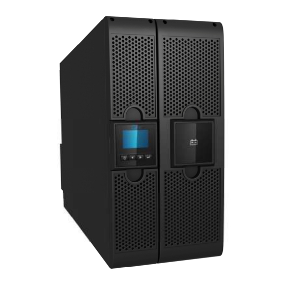
1. Introduction This Online R/T Series is an uninterruptible power supply incorporating double-conversion technology. It provides perfect protection specifically for computer equipment, communication systems to computerized instruments. It protects your sensitive electronic equipment from basic power problems such as power failures, power sags, power surges, brownout, and line noise. - Page 4 Figure 1-2: AP160N-10K-KS Online R/T UPS as Tower installation. Figure 1-3: AP160N-6K-KS Figure 1-4: AP160N-10K-KS Providing outstanding performance and reliability, the UPS’s unique...
- Page 5 benefits include: Online UPS design with pure sine wave output. True online double-conversion technology with high power density, utility frequency independence, and generator compatibility. Intelligent Battery Management technology that uses advanced battery management to increase battery service life, optimize recharge time. Selectable High Efficiency mode of operation.
-
Page 6: Safety Warnings
2. Safety Warnings CAUTION: Before performing the procedures in this document, read and follow the safety instructions and important regulatory information in your Safety, Environmental, and Regulatory Information document. IMPORTANT SAFETY INSTRUCTIONS FOR EACH STEP SAVE THESE INSTRRUCTIONS. 2.1 Installation Condensation may occur if the UPS is moved directly from a cold to a warm environment. -
Page 7: Operation
the neutral conductor should be provided in the building wiring installation. This is permanently connected equipment , it must be installed by qualified maintenance personnel. Earth connection is essential before connecting to the building wiring terminal. 2.2 Operation Do not disconnect the earth conductor cable from the UPS or the building wiring terminals in any time since this would cancel the protective earth of the UPS system and all connected loads. -
Page 8: Transport
measures specified below and any other measures necessary: - remove all jewellery, wristwatches, rings and other metal objects. - use only tools with insulated grips and handles. Please replace the fuse only with the same type and of the same amperage in order to avoid fire hazards. Do not dismantle the UPS, except the qualified maintenance personnel. - Page 9 Low Frequency Signals....:IEC/EN 61000-2-2 Warning: This is a product for commercial and industrial application in the second environment-installation restrictions or additional measures may be needed to prevent disturbances.
-
Page 10: Installation
3. Installation This chapter explains: Equipment inspection Unpacking the cabinet Checking the Accessory UPS setup and installation Connecting the Batteries Installation requirements 3.1 Inspecting the Equipment If any equipment has been damaged during shipment, keep the shipping cartons and packing materials for the carrier or place of purchse and file a claim for shipping damage. - Page 11 Online R/T 6KUPS: Figure 3-1: Unpacking the Cabinet of AP160N-6K-KS UPS Online R/T 10K UPS Figure 3-2: Unpacking the Cabinet of AP160N-10K-KS UPS Step 2: Please lift carefully the cabinet out of the outer carton and set it on a flat, stable surface (see Figure 7&8).
- Page 12 Lifting the Cabinet: Figure 3-3: Lifting the Cabinet of AP160N-6K-KS UPS Figure 3-4: Lifting the Cabinet of AP160N-10K-KS UPS Step 3: Discard or recycle the packaging in a responsible manner, or store it for future use.
-
Page 13: Ups Rear Panel
3.3 UPS Rear Panel This section shows the rear panel of the Online R/T models. 6K model: Figure 3-5: AP160N-6K-KS Rear Panel 10K model: 퍆 䴰 ͠ ѻ Figure 3-6: AP160N-10K-KS Rear Panel... -
Page 14: Ups Front Panel
3.4 UPS Front Panel This section shows the front panel of the Online R/T UPS. The Online series have the same LCD panel and the same control button. Figure 3-7: Front Panel 3.5 Rackmount Setup 3.5.1 To install the UPS 1. - Page 15 3. If installing additional UPSs, repeat Step 1 through Step 2 for each cabinet. 3.5.2 Connecting the Batteries CAUTION: This type of connection must be carried out by qualified electrical personnel. Please connect an appropriate breaker between UPS and batteries. Please use the 10AWG wire to connect UPS and batteries AP160N-6K-KS 1.
- Page 16 2. Connect the batteries and UPS. Fig 3-10: Connecting the UPS and batteries Breaker ͯ 3. Mount the front panel. AP160N-6K-KS 1. Connect the 10 AWG between UPS and batteries breaker.
-
Page 17: Tower Setup
3.6 Tower Setup Tower setup as below: Figure 3-11. Tower setup 3.7 Installation of UPS with AC inputs CAUTION: Online AP160N-6K-KS / AP160N-10K-KS series support that the UPS can have separate AC inputs. So before connecting wires of seperate AC inputs, you should confirm that their earthing systems are identical. - Page 18 UPS with common Normal and Bypass AC inputs UPS with separate Normal and Bypass AC inputs Earthing systems are identical: Earthing systems are separate: ㅆ ͯ Three different installations can be choosen: 1) Transformer in the Normal AC input. 2) Transformer in the Bypass AC input.
- Page 19 3) Both of them have transformer Frequency converter (without Bypass AC input)
-
Page 20: Power Cables Connection & Start Up
4. Power cables connection & Start up This section explains: Access to terminal block Common input sources connection Separate input sources connection Frequency converter connection UPS initial startup 4.1 Access to terminal block Access to terminal block: remove the 2 screws of the terminal block cover Fig 4-1: Remove the terminal block for AP160N-6K-KS Fig 4-2: Remove the terminal block for AP160N-10K-KS... -
Page 21: Common Input Sources Connection
4.2 Common input sources connection CAUTION: This type of connection must be carried out by qualified electrical personnel! CAUTION: Always connect the earthing wire first! ͠ ӱ Figure 4-3: Common input sources conection for 6K Model Figure 4-4: Common input sources conection for 10K Model... -
Page 22: Separate Input Sources Connection
4.3 Separate input sources connection CAUTION: This type of connection must be carried out by qualified electrical personnel! CAUTION: Always connect the earthing wire first! 戀 ѩ Figure 4-5. Separate input sources connection for AP160N-6K-KS Figure 4-6. Separate input sources connection for AP160N-6K-KS... -
Page 23: Frequency Converter Connection
4.4 Frequency converter connection Figure 4-7. Frequency converter connection for AP160N-6K-KS f ͠ ӱ Figure 4-8. Frequency converter connection for AP160N-10K-KS 4.5 UPS Initial Start up To start up the UPS: Verify that the total equipment ratings do not exceed the UPS capacity to prevent an overload alarm. - Page 24 The UPS display panel illuminates and shows a menu of “Welcome” 3. Verify that the UPS transfers to Bypass mode. 4. Press the button on the UPS front panel for at least three seconds. 5. Check the UPS display for active alarms or notices. Resolve any active alarms before continuing.
-
Page 25: Operation
5. Operation 5.1 Display Panel The UPS has a four-button graphical LCD with dual color backlight. Standard back-light is used to light up the display with white text and a blue background. When the UPS has a critical alarm, the backlight changes the text to dark amber and the background to amber. -
Page 26: Display Functions
Press for less than Scroll back or up to the previous one second menu Press for more than Return/exit back one menu layer one second without initiating a command or changing a setting Press for more than Scroll forward or down to the next one second menu option Press for less than... - Page 27 UPS Status A UPS status summary screen replaces the startup screen after the UPS is powered on. The UPS status summary screen displays until you press to go to the first of the main menu selections. The UPS status provides separate screens for the following information: Status summary, including mode and load Notice or alarm status, if any are present...
- Page 28 Normal Mode: I nput Out put The UPS is operating in Normal mode from utility power. The UPS monitors and 200V charges the batteries as needed and 100% 6000 provides filtered power protection to your equipment. Battery Mode: I nput Out put The status icon and background of the icon are flashing.
- Page 29 Bad Battery Detected or Battery I nput Out put Disconnected: : : : Icon and back ground of icon is flashing 200V by inverting colors every second along 100% 6000 with the outer shell of the battery icon at the middle. Alarm:...
-
Page 30: Communication
6. Communication This chapter describes: Communication ports (RS-232 and USB) Network Management Card (Optional) UPS Management Software 6.1 RS-232 and USB Communication Ports To establish communication between the UPS and a computer, connect your computer to one of the UPS communication ports using an appropriate communication cable. -
Page 31: Network Management Card (Optional)
To external device No connection On Battery signal Vdc Power 6.2 Network Management Card (Optional) Network Management Card allows the UPS to communicate in a variety of networking environments and with different types of devices. The Online series has one available communication bay for the following connectivity cards: Connect UPS- MS Web/SNMP Card –... -
Page 32: Ups Management Software
DB-9 Interface of AS400 communication protocol 6.3 UPS Management Software Free Software Download – WinPower WinPower is a brand new UPS monitoring software, which provides user-friendly interface to monitor and control your UPS. This unique software provides safely auto shutdown for multi-computer systems while power failure. - Page 33 Installation procedure: 1. Go to the website: http://www.ups-software-download.com/ 2. Choose the operation system you need and follow the instruction described on the website to download the software. 3. When downloading all required files from the internet, enter the serial No: 511C1-01220-0100-478DF2A to install the software. When your computer restarts, the WinPower software will appear as a green plug icon located in the system tray, near the clock.
-
Page 34: Ups Maintenance
7. UPS Maintenance This chapter explains how to: Care for the UPS Transport the UPS Recycle the used UPS 7.1 UPS Care For the best preventive maintenance, keep the area around the UPS clean and dust-free. If the atmosphere is very dusty, clean the outside of the system with a vacuum cleaner. -
Page 35: Specifications
8. Specifications This chapter provides the following specifications: Model list General Specification Electrical Performance Environmental and Safety Table4. Model list UPS Model AP160N-6K-KS AP160N-10K-KS Table5. General specification Model AP160N-6K-KS AP160N-10K-KS Power Rating 6KVA/5.4KW 10KVA/9KW Frequency (Hz) 50/60 50/60 Voltage (120-276)VAC (120-276)VAC Input Current... - Page 36 Output Voltage Power Frequency Current Distortion Overload capacity Regulation Factor tolerance crest ratio Synchronized 102%-130% load THD<2% 50/60Hz±10% transfers to Bypass Full load in Line mode mode after 2 minutes (Linear (AC mode) Load)/ >130% load transfers 0.9 lag ±1% <5% for maximum ±0.1% of...
-
Page 37: Troubleshooting
9. Troubleshooting The online series UPS is designed for durable, automatic operation and issues alarms to alert you whenever potential operating problems occur. Usually the alarms shown by the control panel do not mean that the output power is affected. Instead, they are preventive alarms intended to alert the user. - Page 38 To access troubleshooting information using the UPS status menu screen: Press the button for one second or longer to go to the UPS status menu screen. Press the button to access the UPS Status Summary screen. Press the button to access the notice and alarm screens. The UPS Status Summary screen provides load information.
-
Page 39: Typical Alarms And Conditions
UPS Status menu displays by default. access troubleshooting information using the Event Log menu: 1 Press the button for one second to go to the main menu selection and scroll down to the Event Log menu using the button. 2 Click the button to enter the Event Log list. - Page 40 Utility Abnormal Utility is out of the tolerance Check input mains condition of input Alarm Code: 02 UPS has a unexpected Back feed Transfer to maintenance bypass current on battery bypass and call service. Alarm Code:93 mode Battery voltage is lower than Verify that all batteries are the batteries disconnected properly connected.
- Page 41 Alarm Code:43 mode because of overload in bypass mode or HE mode. Remove all the loads. Turn off the UPS. Indicates that the UPS has detected abnormally low Check if UPS output and Output Short Circuit impedance placed on its loads is short circuit.
- Page 42 Inv Under Voltage Indicates that the UPS get The UPS transfers to Bypass inverter under voltage fault mode if supporting the load Alarm Code:33 Indicates that the inverter Inv Softstart Fail Contact your service could not soft start representative Alarm Code:34 successfully The UPS turns off the Indicates that the UPS has...
- Page 43 “Redundancy lost” only Parallel system, notice client that system isn’t Redundancy lost Redundancy lost alarm redundancy. Redundancy enable,system load is Alarm Code:ED lost alarm disable can make increase this alarm disappear. 惠 ѹ...
- Page 44 賀 Ӧ 614-08007-01...
Need help?
Do you have a question about the Online R/T Series and is the answer not in the manual?
Questions and answers