
Subscribe to Our Youtube Channel
Related Manuals for Side-Power Stabilizer


Summary of Contents for Side-Power Stabilizer
- Page 1 Operation and User guide Stabilizer Systems US Patent US9527556 AU Patent AU2013335369 Patent pending: PCT/NO2013/050067 Document id: 2950 Revision:...
-
Page 2: Table Of Contents
Alarm list ............................... 7 Alarms and system monitoring ........................... 8 Boat handling restrictions ..........................9 Service and Maintenance ..........................10 Warrany Statement ............................14 All Side-Power products fulfill the requirements of the relevant CE-directives. Stabilizer Operation and User guide version 2950-4 - 2018... -
Page 3: Typical Component Layout
- close to the powerpack. The main ECU with sensors is placed on a bulkhead, central in the boat. (In most cases) The Control Panel is placed on the dashboard(s) of the yacht Stabilizer Operation and User guide version 2950-4 - 2018... -
Page 4: Information
If you leave the fin stabilizer system off so the fins are left in a fixed position, this can make the boat behave differently then expected at high speeds. -
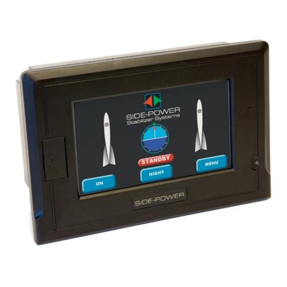
Page 5: Main Menu
Main menu Letters between brackets (x) refer to content headline topic in the Advanced Stabilizer panel PANEL setup.(For installer and distributor only) CONTROL PANEL MAIN screen description: If lit – the system is STATUS IN Shows fin position Shows boat angle... -
Page 6: Settings
Returns to MENU (B) SYSTEM STATUS screen If lit – the system is getting a valid GPS signal (if not the stabilizer will not work) Shows info about: GPS SPEED : the actual speed input from GPS SYSTEM STATE : the state the system is in at present... -
Page 7: Alarms And System Monitoring
Please see the table on the next page for a quick reference to actions to be taken. If in doubt of the meaning or explanation - Please make sure to contact a Side-Power service representative to ensure safe operation of your boat and avoid further potential damage to your systems. -
Page 8: Alarms And System Monitoring
Pressure Sensor Wire There is a break in the 4-20mA sensor loop. Inspect wiring. Break Break Servo Valve current out Servo Valve current out Contact Side-Power for assistance of limits of limits Stabilizer Operation and User guide version 2950-4 - 2018... -
Page 9: Boat Handling Restrictions
Check wiring for shorts or replace sensor. If an alarm occurs so the stabilizer system is not running, but the fins are centred and locked, you can operate the boat normally, remembering the general warning about high speeds and inactive stabiliz- ers as well as ensuring safe engine running without damaging central hydraulic parts - last section in table below. -
Page 10: Service And Maintenance
SERVICE FIN ACTUATOR UNITS The stabilizer system is in general a low maintenance product, but as all moving parts some degree of preventive maintenance will increase the lifetime and reliability of the system. A chart for recommended check and service points is thereby offered at the end of this section. - Page 11 The maintenance schedules in this section indicate the recommended preventative maintenance intervals for equipment supplied by Side-Power. Components utilized in Side-Power Stabilizer Systems but not supplied by Side-Power are not included in the maintenance schedule or under any Side-Power warranty.
- Page 12 Onboard maintenance possible at sea No shore support required Shore supported maintenance and corrective measures Trained personnel required - Side-Power personnel or equivalent Dry - Vessel must be out of water to perform task Wet - Vessel can be in water to perform task A.
- Page 13 250h 500h 2000h 4000h 8000h 12000h required level water 1. Clean the Cooling Fan of the VFD 1/3 W ü 2. Test the Emergency Stop Button 1/3 W ü Stabilizer Operation and User guide version 2950-4 - 2018...
-
Page 14: Warrany Statement
8. The Warrantor assumes no liability for incidental or consequential damages of any kind including damages arising from collision with other vessels or objects. 9. This warranty gives you specific legal rights, and you may also have other rights which vary from country to country. Stabilizer Operation and User guide version 2950-4 - 2018... - Page 15 Stabilizer Operation and User guide version 2950-4 - 2018...
- Page 16 Worldwide sales and service www.side-power.com SLEIPNER MOTOR AS P.O. Box 519 N-1612 Fredrikstad Norway The information given in the document was correct at the time it was published. However, Sleipner Motor AS can not accept liability for any inaccuracies or omissions it may contain.
Need help?
Do you have a question about the Stabilizer and is the answer not in the manual?
Questions and answers