Advertisement
Quick Links
Activate
Your Warranty
By Registering
TODAY!!!
9281 LeSaint Drive • Fairfield, Ohio 45014
Phone (513) 874-2818 • Fax (513) 874-2914
Sales: 1-800-543-7166
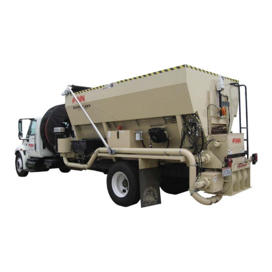
Model BB1216 and BB1222
Operator Instructions and Parts Manual
Model MU
Serial No. _____________
BB1216 - BB1222 MU0518 Rev. A
Advertisement

Related Manuals for Finn Bark Blower BB1216


Summary of Contents for Finn Bark Blower BB1216
- Page 1 Activate Your Warranty By Registering TODAY!!! 9281 LeSaint Drive • Fairfield, Ohio 45014 Phone (513) 874-2818 • Fax (513) 874-2914 Sales: 1-800-543-7166 Model BB1216 and BB1222 Operator Instructions and Parts Manual Model MU Serial No. _____________ BB1216 - BB1222 MU0518 Rev. A...
- Page 2 FOR OFFICE USE ONLY DATE UPDATE DESCRIPTION CODE 01/31/17 Initial release; Updated Hydraulic System; Added Manual Canister to Tool Kit list MU0131 05/18/17 Revision A: New toolbox MU0518...
- Page 3 Labor hours must coincide with the published “Labor Schedule” or estimate approved by the Finn Warranty Administrator. Once work is done, a Finn Warranty Claim Form must be fi lled out and emailed along with any related receipts or invoices to the Warranty Administrator. We ask that this is done ASAP after work is completed.
- Page 5 The FINN Bark Blower and Its Function........
- Page 6 INDEX CONTINUED Clearing a Blockage ........... . .17 Quick Dump Feature.
- Page 7 SAFETY FIRST With any piece of equipment, new or used, the most important part of its operation is SAFETY! FINN Corporation encourages you and your employees to familiarize yourselves with your new equipment and stresses safe operation. The first five pages of this manual are a summary of the main safety aspects associated with this unit.
- Page 8 BARK BLOWER SAFETY SUMMARY SECTION It is important that all operators of this machine are familiar with all the safety aspects mentioned below before operating the machine. Always keep a copy of this manual with the machine. It is the respon- sibility of the operator of the machine to fully understand this safety section.
- Page 9 firm control of the hose. Additional personnel to 17. Be careful in getting on and direct hose may be necessary if working on slopes. off the blower, especially in The proper technique for grasping the hose used by wet, icy, snowy or muddy hose-holding personnel is to route and firmly grasp conditions.
- Page 10 Collect all fluids and dispose of them properly. It is recommended that only authorized, genuine FINN replacement parts be used on the machine.
- Page 11 CURRENT SET OF SAFETY DECALS CAUTION Wear ear protection when operating machine. The sound power level could exceed 80 dB(A) while the unit is in operation. Failure to comply could result in moderate or minor injury. P/N 13184...
- Page 12 NOTES...
- Page 13 FINN BARK BLOWER INTRODUCTION The FINN Corporation would like to thank you for your latest FINN purchase. In our efforts to maintain a quality and growing relationship with each customer, we would like to encourage you to contact us for help with service, genuine replacement parts, or any other information you may require.
- Page 14 NOTICE Mounting the blower to the truck must allow for tire clearance, as well as frame twist. Place hard- wood spacers along the length of truck rails, or use FINN® Spring Mounting Kit (number 011562) or equivalent. Follow mounting instructions given in Figure 1 and Figure 2 on page 9. If mounting conditions require deviation from these instructions, consult the factory.
- Page 15 TRUCK MOUNTING CALCULATIONS: (WB x FL) – (WB x FE) = G Center Of Gravity Ref. WB x (RE + HW - RL) = G G + C must be equal to or less than CA (WB x FE) + (G x BW) = FL (WB x RE) + BW x (WB –...
- Page 16 SELECTING A MULCHING MATERIAL Several factors must be considered when selecting material to convey through the Bark Blower. The variety of the wood used, how it is processed, its moisture content, and the presence of for- eign objects all affect the ability of the Bark Blower to convey the mulch at a uniform and accept- able rate.
- Page 17 Inspect the engine air cleaner (refer to the Engine Operator’s Manual), the radia- tor chaff screen, and the blower air cleaner for dust and dirt. If necessary, clean or replace the air filter. Check hopper and transition for foreign objects that could injure workers or dam- age equipment.
- Page 18 ing four subsystems, all of which contribute to efficient material flow: SUBSYSTEM 1: MATERIAL HANDLING GROUP The four major components of the material handling group are the blower, the drag conveyor, the feed roll, and the airlock. The blower is a rotary lobe, positive-displacement-type unit having two double-lobe impellers. The blower is directly driven off the engine flywheel via a flexible coupling.
- Page 19 FRONT BOTTOM Figure 3 DESCRIPTION OF VALVE SECTIONS Figure 3 shows the valve block and the different hydraulic circuits. Each circuit, except for the Hose Reel (HR) circuit, is controlled by two valves. On the Floor (F) and Airlock (AL) circuits, the flow rate is controlled by the proportional valves.
- Page 20 D. AIRLOCK he last valve section of the manifold runs the airlock. The spool in the valve is factory-set so the airlock turns at about 12 rpm. The proportional valve in combination with the control box, provides adjustment of the airlock speed. There is a pressure switch on the forward circuit that is set for 2,400 psi (16,547 kPa) that triggers the auto-reverse function on the airlock.
- Page 21 SUBSYSTEM 4: RADIO REMOTE TRANSMITTER (RRT) This Bark Blower is equipped with a RRT to control the MATERIAL FEED START/STOP, the FLOOR SPEED, and the ENGINE THROTTLE. It also contains an EMERGENCY STOP button that acti- vates the Murphy shutdown system on the engine. If using the RRT, a certain start-up sequence must be followed to activate the remote.
- Page 22 9. With a firm grip on the end of the hose, press the material start button on the RRT. 10. Floor speed can be adjusted for the desired flow. Watch for auto-reversing of the airlock as well as shock waves through the hose. Listen for the relief on the blower. Partial plug- ging in the airlock discharge or hose may cause it to open, causing a high-pitched whine indicating over-feeding of the airlock.
- Page 23 C. REGULARLY TRIPPING THE BLOWER RELIEF The blower on your machine has a relief valve in the air line. This relief valve protects the blower against a large back-pressure that could build if the line becomes plugged. The relief valve, set for 14 psi (97 kPa), is located directly behind the blower in the engine area on the front of the machine.
- Page 24 CAUTION In Quick Dump mode, the feed roll is exposed and can cause material to be thrown from the rear of the machine, especially at higher floor speeds. Please avoid being near the open gate at the rear of the machine. Failure to comply could reuslt in minor to moderate personal injury.
- Page 25 DAILY - AFTER EVERY 4 TO 8 HOURS OF OPERATION 1. Check engine and blower air cleaner filters for dirt and debris. Remove and clean with dry compressed air if necessary. 2. Check engine coolant and oil levels. Add or replace as necessary. 3.
- Page 26 E) Tighten the nine bolts on the three knife-clamps and replace the set-screw plugs in the access holes. 7. If a knife is worn past adjustment and needs to be replaced, follow the procedure below: A) Remove the nine bolts that hold the three knife clamps in place and remove the clamps and knife.
- Page 27 3. To adjust the chain tension, find the take-up bearings on either side of the floorsill near the front of the hopper. Using a 1-1/2-in. wrench, turn the tensioning rod clockwise to tight- en the chain and counterclockwise to loosen it. Always turn both tension rods the same amount so that the chain is always square with the drive shaft.
- Page 28 NOTES...
- Page 29 TROUBLESHOOTING CHART Symptom Probable Cause Remedy Engine will not start No fuel Check fuel gauge on engine sheet metal. Airlock not turning Safety switch open Make sure rear cleanout door and airlock discharge are closed tightly and interlock switches are working properly.
- Page 30 The key switch on the control box has three positions. From left to right, they are OFF, ON, and START. When the key switch on the control box is turned to the ON position, the FINN loading screen will appear for a few seconds before advancing to the MAIN menu screen (see Figure 7, page 24).
- Page 31 NAVIGATING THE BARK BLOWER INTERFACE NOTE: To return to the MAIN menu at any time, press the Home button on the Main Control Panel (see Figure 6). Figure 7 On the right and left-hand sides of the MAIN menu screen (see Figure 7) are the names of eight sub menus.
- Page 32 Figure 9 While in the PANEL OPERATE menu screen (see Figure 9), the operator can set the Airlock Speed, Floor Speed, and Engine Speed. The Floor, Material, Water (Dust Control), Quick Dump, and Seed Injection (SI) can all be turned either ON or OFF in this menu. The operator also has the ability to choose a preset program in the PANEL OPERATE menu screen.
- Page 33 CHANGING AND SELECTING SEED MIX SETTINGS To change your Seed Injection (SI) settings (if equipped), you will need to access the SI menu screen. To access the SI menu screen, you will need to press the SI Setup button, located in the bottom-right of the SET-UP menu screen (see Figure 8).
- Page 34 CHANGING AND SELECTING SEED MIX SETTINGS To access the DIAGNOSTICS menu screen, press on the button labeled Diag., located on the bottom-right of the MAIN menu screen (see Figure 7). Figure 12 The DIAGNOSTICS menu screen displays engine information read from the engine’s ECU (see Figure 12).
- Page 35 CHANGING THE MASTER SETTINGS To change the master settings on your Bark Blower, you will need to press the button labeled Master Settings, located in the MAIN menu screen (see Figure 14 below). Figure 14 Once you have pressed the Master Settings button, you will be taken to the Pass Code screen (see Figure).
- Page 36 Figure 16 In the MASTER SETTINGS menu (see Figure 16), you can change all of the settings to meet your needs. There are two pages located in the MASTER SETTINGS menu. To change between pages, press the button labeled Page. If you want to change any settings, use the control knob located on the Main Control Panel.
- Page 37 NOTES...
- Page 38 LUBRICATION LOCATIONS Figure 7...
- Page 39 LUBRICATION CHART Ref. No. Location Lubricant Frequency Number Airlock Bearing Weekly Change Airlock Gearbox Oil 50,100, then Seasonally Feeder Roll Bearing Weekly Floor Pillow Block Bearing Weekly Floor Take-Up Bearing Weekly Check Blower Inlet Filter Daily Check Engine Air Cleaner Daily Check Engine Coolant Level Daily...
- Page 40 NOTES...
- Page 41 NOTES BARK BLOWER Model 1216 and 1222 Parts Manual Model MU BB1216 - BB1222 MU0131...
- Page 42 16 Cu. Yd. Hopper Shown LOOSE PARTS Ref. No. Part Number Description No. Req'd 011770 Battery Box 011851 Battery F400-0031 Battery Tray F400-0038 Battery Holddown Strap 053157 Hydraulic Reservior 011927 Hydraulic Reservoir Suction Strainer 008706 Hydraulic Reservoir Fill Cap 012693 Fuel Tank 012694 Fuel Level Sender...
- Page 43 AGITATOR ASSEMBLY Ref. No. Part Number Description No. Req'd 052873-02 Agitator Assembly (Includes Items 1 thru 5) 052872-01 Agitator Shaft 052420 Special Agitator Stub Shaft 0X1260 3/4-10 UNC HHCS x 3-3/4 in. Lg. 00X12L 3/4-10 UNC Lock Nut 00W12L 3/4 in. Lock Washer 0X1040 5/8-11 UNC HHCS x 2-1/2 in.
- Page 44 WHEN ORDERING PARTS, BE SURE TO STATE SERIAL NUMBER OF MACHINE BB1216 - BB1222 MU0518 Rev. A...
- Page 45 FLOOR AND FEED ROLL PARTS Ref. No. Part Number Description No. Req'd 052500 Feed Roll Hydraulic Motor 045031 Feed Roll Mount Hub 052676 Feed Roll 052517-01 Left-Hand Feeder Panel F916-0004 Feeder Top Cover 052517-02 Right-Hand Feeder Panel 020586 2-Bolt Feed Roll Bearing 052506-01 Top Feeder Door Hinge F916-0006-01...
- Page 46 WHEN ORDERING PARTS, BE SURE TO STATE SERIAL NUMBER OF MACHINE BB1216 - BB1222 MU0518 Rev. A...
- Page 47 AIRLOCK PARTS Ref. No. Part Number Description No. Req'd 053192 18 x 33 Standard Duty Airlock 053202 18 x 33 Heavy Duty Airlock (option) 052754 Flange Bearing 053200 Knife, 18 x 33 Airlock 053201 Knife Clamp, 18 x 33 Airlock 052535 Airlock Hydraulic Motor 045378...
- Page 48 VIEW A REF: ENGINE SHEET METAL WHEN ORDERING PARTS, BE SURE TO STATE SERIAL NUMBER OF MACHINE BB1216 - BB1222 MU0518 Rev. A...
- Page 49 VIEW A ENGINE AND RADIATOR Ref. No. Part Number Description No. Req'd 023916 4045T Tier 3 Engine Assembly JDR524005 Fan Belt JDSD443 Fan Spacer JDART24834 Pusher Fan F330-0135 Radiator Arm Support Bracket 023438 Rubber Mount F330-0131 Radiator Support Bracket JDSD284 Fan Guard JD50-0532 Radiator...
- Page 50 WHEN ORDERING PARTS, BE SURE TO STATE SERIAL NUMBER OF MACHINE BB1216 - BB1222 MU0518 Rev. A...
- Page 51 ENGINE SHEET METAL Ref. No. Part Number Description No. Req'd 055669 Lock Positioning Hinge F260-0006-02 Radiator Cap Cover F260-0006-03 Hinge Spacer F1216-0027 Radiator Shroud F1216-0012 Radiator Screen F1216-0031-01 Left Radiator Shroud Mount F1216-0031-02 Right Radiator Shroud Mount F1216-0030 Engine Exhaust Cover F170-0020 Radiator Pan 012753...
- Page 52 ENGINE AIR INTAKE Ref. No. Part Number Description No. Req'd 055496 AC 300 Clamp 055498 Hump Adapter #RH430 055335 AC 400 Clamp 053084 Air Cleaner Tube 055367 Hump Adapter #RH440 013135 Engine Air Cleaner Assembly 013135-M Main Filter Element 013135-M Safety Filter Element WHEN ORDERING PARTS, BE SURE TO STATE SERIAL NUMBER OF MACHINE...
- Page 53 Engine Blower Shaft *Note: Part number 045003 blower coupling half must be locked with double setscrews (two on top of each other.) BLOWER DRIVE ASSEMBLY Ref. No. Part Number Description No. Req'd 045039 Flywheel 045002 Flywheel Mount Coupling Half 045004 Coupling Insert Z0606CPK Coupling Set Screw...
- Page 54 WHEN ORDERING PARTS, BE SURE TO STATE SERIAL NUMBER OF MACHINE BB1216 - BB1222 MU0518 Rev. A...
- Page 55 BLOWER SYSTEM Ref. No. Part Number Description No. Req'd 052905 Pre-Cleaner 052905-C Pre-Cleaner Clamp 052907 Filter Bracket 052905-B Pre-Cleaner Bushing 053001 Outlet Silencer 052919-02 Inlet Tube 052906 Canister Filter 052908 7 in. Band Clamp 052915 7 in. Rubber Elbow 052919-01 Blower Inlet Flange 045192-01 Blower Gasket...
- Page 56 WHEN ORDERING PARTS, BE SURE TO STATE SERIAL NUMBER OF MACHINE BB1216 - BB1222 MU0518 Rev. A...
- Page 57 BLOWER PIPING Ref. No. Part Number Description No. Req'd 052981-01 1208/1216 Short Air Tube Weldment 045338 5 in. 90° Elbow 045362 5 in. 45° Elbow Segment 052981-03 Long Air Tube Weldment 053173-02 1216 Air Tube Weldment 045339 5 in. 45° Elbow 052981-04 Connector Air Tube Weldment 052981-02...
- Page 58 WHEN ORDERING PARTS, BE SURE TO STATE SERIAL NUMBER OF MACHINE BB1216 - BB1222 MU0518 Rev. A...
- Page 59 HYDRAULIC SYSTEM Ref. No. Part Number Description No. Req'd A0955-001 Hyrdraulic Hose and Fitting Kit 053148-02 Tubing 3/8 OD X .035 Wall SS 011504 Lenz #8PN 012044 Pressure Gauge #CF-5000-25 012091 Lenz #A3405-12 012103 Lenz #STP-06 012362 Lenz #12 STP Plug 012419 Midstate #6505-04-04 041053...
- Page 60 WHEN ORDERING PARTS, BE SURE TO STATE SERIAL NUMBER OF MACHINE BB1216 - BB1222 MU0518 Rev. A...
- Page 61 HYDRAULIC SYSTEM Ref. No. Part Number Description No. Req'd 053015-09 3/8 in. 100R17 Hose w/ #6 053045-03 3/4 in. 100R17 Hose w/ #12 053045-04 3/8 in. 100R17 Hose w/ #6 053045-05 3/8 in. 100R17 Hose w/ #6 053045-06 3/8 in. 100R17 Hose w/ #6 053045-07 1/2 in.
- Page 62 WHEN ORDERING PARTS, BE SURE TO STATE SERIAL NUMBER OF MACHINE BB1216 - BB1222 MU0518 Rev. A...
- Page 63 CONTROL BOX HARNESS Ref. No. Part Number Description No. Req'd 053060 Control Box Wiring Harness 053017 Deutsch #HD36-24-31ST 053042 Deutsch #34-18-14PT Receptacle 170019 SINGLE CIR RECEPT HSG 480054-3 170023 FASTON RECEPT #42282-2 170101 Deutsch #HDP26-24-21SE Plug 190051 WIRE 16GA BLACK SAE SXL 48 in.
- Page 64 WHEN ORDERING PARTS, BE SURE TO STATE SERIAL NUMBER OF MACHINE BB1216 - BB1222 MU0518 Rev. A...
- Page 65 VALVE WIRING HARNESS Ref. No. Part Number Description No. Req'd 045136 Lighted DIN (2+GND) 053042 18-14PT Receptacle 170004 Ring Tongue 16-14 1/4 170018 Single CIR HSG 170019 Single CIR Recept HSG 170022 170023 Recept 190055 Wire 16GA Green SAE SXL 2 in.
- Page 66 ENGINE WIRING WHEN ORDERING PARTS, BE SURE TO STATE SERIAL NUMBER OF MACHINE BB1216 - BB1222 MU0518 Rev. A...
- Page 67 ENGINE WIRING WHEN ORDERING PARTS, BE SURE TO STATE SERIAL NUMBER OF MACHINE BB1216 - BB1222 MU0518 Rev. A...
- Page 68 ENGINE WIRING WHEN ORDERING PARTS, BE SURE TO STATE SERIAL NUMBER OF MACHINE BB1216 - BB1222 MU0518 Rev. A...
- Page 69 ENGINE WIRING WHEN ORDERING PARTS, BE SURE TO STATE SERIAL NUMBER OF MACHINE BB1216 - BB1222 MU0518 Rev. A...
- Page 70 WHEN ORDERING PARTS, BE SURE TO STATE SERIAL NUMBER OF MACHINE BB1216 - BB1222 MU0518 Rev. A...
- Page 71 DUST CONTROL SYSTEM Ref. No. Part Number Description No. Req'd 052718 75 Gal. Poly Tank 052750 3/4 in. Bulkhead Fitting - Drain 052751 3/4 in. Drain Plug 052718-03 Tank Cap 052842 Poly Reducing Poly Elbow 052841 Reducer Bushing 011504 Pipe Nipple 070122 1/2 in.
- Page 72 WHEN ORDERING PARTS, BE SURE TO STATE SERIAL NUMBER OF MACHINE BB1216 - BB1222 MU0518 Rev. A...
- Page 73 HYDRAULIC HOSE REEL Ref. No. Part Number Description No. Req'd 053194 Hydraulic Hose Reel Assembly 053195 2 in. Special Pillow Block Brg. 052416 Reel Weldment 070660 Hydraulic Motor F1216-0019 Hose Reel Motor Mount 053193 Hose Reel Shaft 053013 Hose Reel Latch 052350-02 Latch Handle Rod 052384-05...
- Page 74 TOP VIEW DRIVERS SIDE PASSENGER SIDE REAR VIEW WHEN ORDERING PARTS, BE SURE TO STATE SERIAL NUMBER OF MACHINE BB1216 - BB1222 MU0518 Rev. A...
- Page 75 Description No. Req'd 011690 FINN Name Plate 023174 Decal "FINN" Large 055639 Decal "Bark Blower" 031235 Decal "FINN" Medium Red 190136 2 in. Red-White Warning Tape 40 ft. Decal "Service Daily" Decal "Service Daily" Decal "Service Weekly"...
- Page 76 MANUAL RESET BREAKER 12 GA (Red) START *(Black) 6 GA (Red) GEAR AUTO-RESET MOTOR BREAKER (Orange) 12 GA (Red) *(Black w/White Stripe) GROUND @ (Black) 12 GA (Black) STARTER BOLT INDICATOR LIGHT TARP ASSEMBLY Ref. No. Part Number Description No. Req'd 052588 Tarp Assembly Includes: RR1031...
- Page 77 TOOL KIT Part Number Description No. Req'd 012681A FINN Beige Touch-Up Paint (Aerosal - 4.5 Oz.) 012681T FINN Beige Touch-Up Paint (Wet - 0.5 Oz.) Engine Parts Manual Engine Operators Manual Blower Operators Manual Radio Remote Control Manual Bark Blower Operator Instructions and Parts Manual...
Need help?
Do you have a question about the Bark Blower BB1216 and is the answer not in the manual?
Questions and answers