Table of Contents
Advertisement
Quick Links
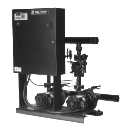
BELL & GOSSETT
70E/70M Multiple Pump & Control
Pressure Booster Systems
Installation, Operation, & Maintenance Instructions
INSTALLER: PLEASE LEAVE THIS MANUAL FOR THE OWNER'S USE.
DESCRIPTION
Microprocessor controlled frame mounted multiple pump
pressure boosting system with combination pressure reducing
and non-slam check valves for maintaining system pressure.
The motors are controlled by a control panel with micro-
processor, starters, overload protection, virtual H-O-A switches,
optional short circuit protection, and control transformer.
The microprocessor control consists of an operator interface
with 2 line backlit display and membrane key pad, input/
output board with 24V power supply, and microcontrolled
kW transducer.
®
INSTRUCTION MANUAL
70E
OPERATIONAL LIMITS
See unit nameplate for pump capacity, boost, full load current
draw, and operating voltage. The pump discharge pressure
must not exceed 125 PSI unless special piping modifications
are made.
SAFETY
INSTRUCTION
This safety alert symbol will be used in this manual and on the
70E/70M Safety Instruction decal to draw attention to safety
related instructions. When used, the safety alert symbol means
ATTENTION! BECOME ALERT! YOUR SAFETY IS
INVOLVED! FAILURE TO FOLLOW THESE INSTRUCTIONS
MAY RESULT IN A SAFETY HAZARD!
S12228
REVISION A
Bell & Gossett
®
Advertisement
Table of Contents

Subscribe to Our Youtube Channel
Summary of Contents for Bell and Gossett 70E
- Page 1 24V power supply, and microcontrolled kW transducer. This safety alert symbol will be used in this manual and on the 70E/70M Safety Instruction decal to draw attention to safety related instructions. When used, the safety alert symbol means ATTENTION! BECOME ALERT! YOUR SAFETY IS...
- Page 2 Permanent records for this unit are kept by the factory number and it must therefore be used with all correspondence and spare parts orders. Model No. Factory No. Wired for Volts System FL Amps Largest Motor HP System Flow GPM Suction Pressure PSIG Discharge Pressure PSIG Pump TDH Feet FIGURE 1 - 70E/70M NAMEPLATE...
- Page 3 Preface The following manual describes the 70E/70M Pressure Boosters with emphasis on the new micropro- cessor based Technologic Controller. This unit is in the tradition of the other members of the Technologic Control Panels as it incorporates many original, novel, and proprietary features that may only be found on B&G controllers.
-
Page 4: Table Of Contents
TABLE OF CONTENTS SECTION 1 – GENERAL Purpose of Manual ..............Safety Instruction . - Page 5 Procedure for Field Balancing 70E/70M PRV’s ........
-
Page 6: Section 1 - General
Inspect the SAFETY HAZARD. unit thoroughly for damage upon receipt. 1.1.4 Your Technologic 70E/70M Series Pump Controller Transportation damage should be brought to the car- should have a safety instruction decal (Part #S11550). rier’s attention immediately. Ensure that sensing lines If the decal is missing or illegible contact your local are free of crimps and kinks. -
Page 7: Field Connection Diagrams
UNIT SUPPORT AND LOCATION are to be checked for tightness. Flanged joints should The Bell & Gossett Series 70E/70M Pressure Booster be checked for proper torque of all flange bolts prior should be installed where there will be sufficient room to filling the system with fluid. -
Page 8: Analog Signal Wiring
2.7.1 POWER WIRING AND WIRING (Digital Signal) (Optional) The 70E/70M Pump Control Panel can be set up to Differential pressure switches installed to sense the operate across a broad range of voltages. It was fac- increase in pressure between the pump suction and... -
Page 9: Section 4 - Setup And Features
SECTION 4 – SETUP AND FEATURES GENERAL NOTES 4.2.3 The operator interface will display the ITT Bell & Gossett corporation signature. 4.1.1 The HELP key can be pressed at any time without disrupting system operation. The HELP key will give 4.2.4 The operator interface will perform a lamp test and details on alarm conditions or if used in conjunction... - Page 10 Default Allowable Field Line # DISPLAY Value Range Values Pump 2 AMPs 0 0 - 175 Enter Motor #2 nameplate FLA Pump 3 AMPs 0 0 - 175 Enter Motor #3 nameplate FLA Pump #1 GPM 0 0 - 30,000 Enter Staging GPM of Pump #1 Pump #2 GPM 0 0 - 30,000...
- Page 11 Low Suct. Auto RST Yes To change the Low Suction reset, use UP/DOWN key to enter yes or no System Press. Span 300 0 - 999 Enter value equal to system pressure span High Sys. Press. 125 Enter value of the high system pressure above 0 - SPAN which an alarm will be set High Sys.
-
Page 12: Key Functions
TEMP Xmitr Span Enter value equal to remote temperate transmitter span. Note this input is used for temperature staging requiring a 4-20mA temperature transmitter. Stage TEMP Rise Select yes to stage pumps on temperature rise based on setpoint. Temp Staging H Enter the high temperature for staging/destaging. -
Page 13: Normal Operating Messages
NORMAL OPERATING MESSAGES 4.5.1 NORMAL SCROLL AUTO OR HAND LOCAL OR REMOTE MESSAGE CONDITION Alternation “None” According to menu entry for simplex, duplex or triplex. “1-2, 2-1” “1-2-3 2-3-1” 3-1-2 “1-2-3 1-3-2” Elapsed Time P1 Hours Elapsed Time P2 Hours If 2 pumps selected Elapsed Time P3 Hours If 3 pumps selected... -
Page 14: Alarms
4.5.2 ALARMS ALARMS CONDITION HELP MESSAGE Overload X Failure Check AMP draw, use manual reset if OK High Suction PSI High suction pressure – check suction pressure and trip point Low Suction PSI Low suction detected – check suction pressure and trip point High System PSI High pressure detected in the system –... -
Page 15: Section 5 - Operation
B. “ITT Bell & Gossett” 6. Timed de-stage is on. “Pressure Booster” 7. Starter feedback is not on. C. “Technologic 70E” “Pump Controller” The 3rd pump stages in the same manner as the sec- D. “Copyright 1995” ond pump according to the menu entry for that pump. -
Page 16: Manual Operation (Cpu Ok)
(CPU Fails, Watchdog LED On) the sequence will start. “Alarm” message flashes. Manual reset. Upon manually resetting the tripped The 70E/70M has a redundant feature allowing criti- starter and pushing the reset key the previously cal operation even though the microprocessor and its tripped starter starts it pump and the pumps run support I.C.’s may have failed. -
Page 17: Section 6 - Maintenance Preface
6 of these terminals used to connect to the 24 DIAGNOSTICS (Service Test) VDC power supply. The Technologic 70E/70M has built in I/O diagnostic It is not recommended that other power sources capabilities activated with a SERVICE TEST key while be used without factory approval. -
Page 18: Read Only Analog Inputs
6.9.3 Interpretation – compare the status shown to the Source 2 Wire following terminals and the wiring diagram. For *Step Signal Input Terms Terms example, starter 1M “on” signal at J4 4 and 8 is dis- Suction 1-, 2+ 2-, 3+ play No. -
Page 19: Pre-Determined Fault And Fault Control
Analog inputs – the analog inputs provided on the (relay coil energized) and a “0” = off. Toggle output Technologic 70E/70M must be wired according to the with a numerical key to match the output #. wiring diagram that shipped with the unit. - Page 20 6.15.3 CONDITION: I/O Error on the display and pump 2 6.15.9 LEDs Malfunction red LED is on. Watch dog LED CR6 is on. A. Observe that all LEDs turn on during the booting Corrective Action: process. Watch dog LED CR6 is off. Pumps will run in manual operation according to Corrective Action: paragraph 5.4 above.
-
Page 21: Instruments And Their Use
6.15.13 Flow Transducer Fault 6.17 FIELD REPAIR A. Alarm per 4.5.2 indicates this fault. 6.17.1 General – field repair, except replacing fuses, replac- B. Scroll of GPM shows flow as: ??? ing analog input resistors, and assuring connections, C. Confirm with analog input test of CHNL 2 per 6.10.3. such as ribbon cable, are correct and secure, is not recommended. -
Page 22: System Piping And Unit Installation - Final Check List
APPENDIX A APPENDIX B SYSTEM PIPING AND UNIT ELECTRICAL WIRING AND CONTROL INSTALLATION – FINAL CHECK LIST SETTINGS – FINAL CHECK LIST ____ 1. Is the unit base properly leveled, grouted and ____ 1. Does the feeder line voltage correspond to the unit secured? voltage? Check the unit nameplate or motor terminal connection. -
Page 23: Procedure For Field Balancing 70E/70M Prv's
The pressure reducing valves are “factory set” on valve setting. The display should now read the 70E and 70M systems, therefore, change of setting desired system pressure. Tighten jam nut and replace may be required. If needed, the following items cap. -
Page 24: Troubleshooting Combination Pressure Reducing And Check Valves
APPENDIX D TROUBLESHOOTING COMBINATION – PRESSURE REDUCING AND CHECK VALVES System Pressure Higher than Desired Set Point e) Leak into upper diaphragm chamber. Close stop cock (Item 7) and remove a connection between Primary Causes the flow control valve (Item 4) and the PRV valve a) Insufficient pressure on top side of diaphragm. - Page 25 APPENDIX D (continued) PRV Does Not Close (Check) on Pump Shut Down Balancing the Settings Primary Causes a) Between two or more equal pumps: 1. Check the motor amps of each pump quickly a) Insufficient pressure on top of diaphragm. (to reduce the possibility of load changes dur- b) Leak through main valve seat or diaphragm ing reading) with both or all equal size pumps...
-
Page 26: Prv Repair Kits
PRV REPAIR KITS Table I: Complete Valve CLA-VAL Model 90-01A - 125#, epoxy coated, bronze trim valves with 30-300# pilot (CRD) spring range. B&G Part No. Size Angle Style (for 70M) Globe Style (for 70E) S11230 S11882 2 Flanged S11231 S11883 Flanged... -
Page 27: Appendix E Service Test Overview
True Turn power off and confirm it is off with a voltmeter. power, amps, and volts are transmitted continuously Lock-out disconnect/s. to the 70E/70M OIP microprocessor. These values are then used for staging and/or display. DO NOT: –... - Page 28 CURRENT SENSING B. Insert this conductor into the hole on the flat side of the doughnut with the load side of the conduc- This is accomplished by inserting one common tor coming out of the opposite side of the hole. power conductor through a linear output Hall effect C.
Need help?
Do you have a question about the 70E and is the answer not in the manual?
Questions and answers