Table of Contents
Advertisement
Quick Links
GuitarPCB.com
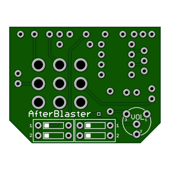
AfterBlaster - Build Instructions
The AfterBlaster is a cool THREE-IN-ONE circuit that provides several useful functions. It is a handy bypass footswitch wiring
board with a status LED. It has a switchable boost circuit that provides a clean boost enhancement for any circuit. It can also
provide a final tone balancer to attenuate the output level of any circuit. Or anything in between!
Add an extra gain stage to any circuit and more .
The DIP switches and trimmer must be installed on the opposite side of the PC board from the other components and footswitch. See the views
below. The left view should be facing up when viewing the gut shot of the pedal. DIP SWITCHES are usually available in our
S HOP.
PARTS LIST
Build Notes:
* B e sure to Socket R4 – See build notes below for details. 2.4k is only an average value to get MPF102, J113 or 2N5457 close to the
wanted 4.5v to 6v reading on the Drain leg of Q1. Google for the Datasheet for whatever transistor you are using.
** Q1 - You may use a J113 (MPF102 replacement) or change to a 2N5457 for more grit, however 2N5457 will require an
adjustment to the value of R 4 . Use a D MM and switch to D CV. Black Probe on ground and Red on the Drain of Q1. Adjust your
socketed R4 value till you get a reading between 4.5v to 6v on the Drain of Q1. T his is easy but important to get the best tone.
*** R5 is the CLR (current limiting resistor. Adjust this value to suit for brightness. Between 1k8 and 4k7 Bright to Dim.
Advertisement
Table of Contents

Related Manuals for GuitarPCB AfterBlaster

Summary of Contents for GuitarPCB AfterBlaster
- Page 1 AfterBlaster - Build Instructions The AfterBlaster is a cool THREE-IN-ONE circuit that provides several useful functions. It is a handy bypass footswitch wiring board with a status LED. It has a switchable boost circuit that provides a clean boost enhancement for any circuit. It can also provide a final tone balancer to attenuate the output level of any circuit.
- Page 2 D ip S mall Bear ● To activate the AfterBlaster both Number 1 Switches should be in the O N position, and both Number 2 switches should be in the O FF (or facing Number 2) position. ●...
- Page 3 Insert the LED leads into the corresponding pads as shown above. If you wish to change the color of the On Status then simply flip the LED to change to the cathode of the color you wish to use. R5 is the Current Limiting Resistor. Use a value from 1k8 to 4k7. TIP: Use a 3v to 5v coin battery to test your LED before installing.
- Page 4 Mod: ** A side from using the on-board Dip Switch and Trimmer (some people prefer the set and forget method) you may use a DPDT switch and potentiometer for mounting on the outside of the enclosure. Keep in mind that the potentiometer should be at roughly 2:00 for unity gain and higher for boost and clarity.
- Page 5 Main Menu Bar of most pages. Also we have a dedicated forum for questions about your build. This document, PCB, Artwork and Schematic Artwork © GuitarPCB.com. Schematic and PCB design by Bruce R and Barry. Build Document by Barry. All copyrights, trademarks, and artworks remain the property of their owners.
Need help?
Do you have a question about the AfterBlaster and is the answer not in the manual?
Questions and answers