Table of Contents

Related Manuals for NetterVibration NTK Series


Summary of Contents for NetterVibration NTK Series
- Page 1 Feb. 2021 Operating instructions for No. 1977E Netter pneumatic linear vibrators Page 1/24 Series NTK These operating instructions apply to: NTK 8 AL NTK 28 AL NTK 15 X NTK 40 AL NTK 16 NTK 40 NTK 18 AL NTK 55 AL NTK 18 AL M1 NTK 55 NTK 25 AL...
-
Page 2: Table Of Contents
Contents General information Safety Technical data Design and function Transport and storage Installation Start-up and operation Maintenance and servicing Troubleshooting Spare parts and accessories Disposal Please refer to the delivery note for the scope of delivery. Scope of delivery Check the packaging for possible transport damage. In the event of damage to the packaging, check the contents for completeness and possible damage. -
Page 3: General Information
General information General information Before installing the NTK read these instructions carefully. It is the basis Use and for any action when dealing with the NTK, and may be used for training storage purposes. The instructions should be subsequently stored at the operation site. - Page 4 General information • NTK NF: low frequency models • NTK HF: high frequency models The pneumatic linear vibrators of the series NTK comply with the EC Ma- Directives / chinery Directive 2006/42/EC. standards observed In particular, the standard EN ISO 12100 has been observed. Instruction The following instruction and warning symbols are used in these instruc- and warning...
-
Page 5: Safety
Safety Safety The NTK are intended for generating linear vibrations. Intended use General applications are: loosening, conveying, sorting, compacting, sepa- rating bulk materials and reducing friction. NTK are used for emptying bunkers, as drives for conveyor troughs, sieves and vibrating tables. The NTK are designed for installation in machines and may only be put into operation, if it has been assured that the complete machine complies with the regulations of the machinery directive. - Page 6 Safety Compressed WARNING Compressed air A loosened hose which is under pressure can lead to personal injuries. ➢ Screw the hose lines on carefully. ➢ Check the hose lines and connections after one hour of operation and thereafter regularly (generally monthly). ➢...
-
Page 7: Technical Data
Technical data Technical data Permissible Drive medium NTK must be operated with clean, lubricated compressed air or lubri- cated nitrogen according to the following specification (according to operating ISO 8573-1): conditions [ 5 : Filter ≤ 5 µm Humidity, pressure Total oil content dew point ≤... - Page 8 Technical data Freely swing- The following table distinguishes between three versions: ing part The piston swings freely. The housing is screwed to the mass to be vibrated. Housing Piston Additional oscillating weight The piston with an additional oscillating weight swings freely.
- Page 9 Technical data Parameters Type Oscillating Frequency Centrifugal Unbalance NTK / weight* consumption force Freely oscillating part [kg] [l/min] [min [cmkg] 2 bar 6 bar 2 bar 6 bar 2 bar 6 bar 2 bar 6 bar 8 AL 0.030 2,440 3,657 0.05 0.06...
- Page 10 Technical data Sound level The sound pressure level is 64 - 79 dB (A) at an air pressure of 6 bar, de- pending on the type (with silencer), and lower at a lower air pressure. Service life The technical performance data changes over the service life (wear and contamination).
- Page 11 Technical data Dimensions for other types ØA HK / ØK M ** Q *** 15 X 23.5 M 10 G 1/8 G 1/8 21.5 M 10 G 1/8 G 1/8 18 AL 25.0 M 10 G 1/8 G 1/8 18 AL 25.0 M 10 / G 1/8...
- Page 12 Technical data Netter Vibration recommends the following tightening torques for fastening Tightening torques screws and nuts of the strength class 8.8 (sliding friction coefficient 0.14): Type: Thread Tightening torque* [Nm] 8 AL Housing Piston 15 X Housing/piston M 10 16, 18 AL Housing/piston M 10 18 AL M1...
-
Page 13: Design And Function
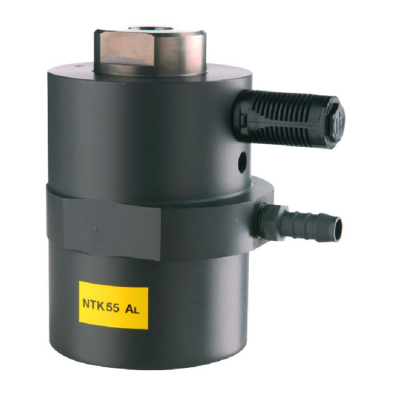
Design and function Design and function Design Cover Piston Housing Additional oscillating weight (optional) Air inlet/grommet Chamber A Air outlet/silencer Chamber B The NTK generate linear vibrations. Function The vibration is generated by a freely oscillating, self-reversing piston. Both weights, the piston (5) with an additional oscillating weight (6) on the one hand, the housing (2) and the weight to which it is attached on the other, oscillate in relation to their total weights against each other. -
Page 14: Transport And Storage
Transport and storage Transport and storage Special conditions of transport are not required. Transport conditions Use suitable lifting equipment to move the NTK 85 E and the NTK 110 E. A transport lug can be screwed into Be careful the piston or into the housing (M 20 when lifting and lowering thread) when lifting. -
Page 15: Installation
Installation Installation Observe the safety instructions in chap. Safety, from page 5 on. Standard- installation Maintenance unit Additional weight (optional) 3/2-way valve Special circuit diagrams are available on request. Technical data Information regarding tightening torques for screws as well as cross sec- tions for valves and hoses can be found in Ch. - Page 16 Installation or liquid sealant. Notice: Do not use sealing tape for the screw con- nections. Do not use longer screw threads for the air supply than in- tended (e.g. no pipes with external thread). Otherwise, the housing may become deformed and the piston may jam. Fasten the compressed air supply securely.
- Page 17 Installation Supported For inclined or horizontal mounting of the NTK, the vibration vibration mass of the freely oscillating part S1, S2 or mass S3 (see section Parameters, page 9) may only ex- ceed the following value if the vibration mass is sup- ported by a spring: Type Vibration mass to...
- Page 18 Installation Checklist Check that the following steps have been carried out: installation Compliance with permissible ambient temperatures ensured? Central fastening screw with suitable lock washer installed? Screw size and tightening torques observed? Additional medium-strength liquid safety agent for securing the screw connections used? Maintenance unit (filter, regulator, mist lubricator*), valve and supply line installed?
-
Page 19: Start-Up And Operation
Start-up and operation Start-up and operation Observe the safety instructions in chap. Safety, from page 5 on. Please refer to chap. Technical data, page 7 for permissible operating Permissible conditions. operating conditions Setting the The frequency of the NTK should be set with the pressure regulator of the frequency maintenance unit. - Page 20 Start-up and operation Checklist Check that the following steps have been carried out: start-up Screw connections checked before start-up? Desired frequency set on pressure regulator? Desired amplitude set by throttling the exhaust air? Mist lubricator set? After one hour of operation: Hose supply connections as well as fastening screws checked, retightened, if necessary? Then follow the maintenance plan.
-
Page 21: Maintenance And Servicing
Maintenance and servicing Maintenance and servicing Observe the safety instructions in chap. Safety, from page 5 on. If necessary clean the surface of the NTK with a moist cloth to remove Cleaning dust deposits. To clean the NTK with pressurised water, proceed as follows: Close the supply air and exhaust air openings. -
Page 22: Troubleshooting
Troubleshooting Troubleshooting In the case of malfunctions of the NTK proceed as follows: Malfunctions and causes Malfunction Possible cause Corrective action No start Silencer polluted Clean silencer. Compressed air Check if there is enough pressure at the NTK. Check supply valve. -
Page 23: Spare Parts And Accessories
Spare parts and accessories 10 Spare parts and accessories There are no spare parts available for the NTK. If necessary, have the Spare parts Netter Vibration. NTK checked by Possible The following accessories are available for the NTK: accessories Accessory Description Additional swing weights SM For all NTK in different sizes... -
Page 24: Disposal
Disposal 11 Disposal Prices All parts of the NTK must be properly disposed of according to the material specifications. The valid disposal prices of the NTK are available on request. All parts of the NTK can be recycled. Material specifications Material Part Aluminium (for NTK AL)
Need help?
Do you have a question about the NTK Series and is the answer not in the manual?
Questions and answers