Table of Contents
Advertisement
Advertisement
Table of Contents

Summary of Contents for ROBOTIQ UNI-CTR-001 Series
- Page 1 © ROBOTIQ INC. 2014 Get the latest version of the manual at support.robotiq.com...
-
Page 2: Table Of Contents
11. Contact ....................41 Robotiq inc. © 2008 - 2014... -
Page 3: Revisions
Information provided by Robotiq in this document is believed to be accurate and reliable. However, no responsibility is assumed by Robotiq for its use. There may be some differences between the manual and the product if the product has been modified after the edition date. -
Page 4: General Presentation
. The Robotiq Universal Controller is a robotic peripheral controller for other Robotiq devices and communication with other robot controllers. The Universal Controller is designed for industrial applications with various communication protocols and is common to all Robotiq devices. Note... - Page 5 Communication connection for details on the Communication Panel. The Robotiq User Interface can be used via the standard USB 2.0 port to control or configure Robotiq devices. Visit http://support.robotiq.com to get the latest installer of the Robotiq User Interface along with appropriate documentation.
-
Page 6: Safety
Decommissioning This documentation explains the various components of the Universal Controller and its general operation. Read this documentation and the associated Robotiq Gripper device documentation and be sure to understand its contents before handling the Controller or Gripper. The drawings and photos in this documentation are representative examples and differences may exist between them and the delivered product. -
Page 7: Warning
Any use of the Controller in noncompliance of these warnings is inappropriate and may cause injury or damage. Warning Concerning Controller use in a robot environment (with robot and/or Robotiq Grippers): Respect all robot safety recommendations. Respect all Gripper safety recommendations. -
Page 8: Intended Use
Robotiq Universal Controller Instruction Manual 2.2 Intended use The Controller unit is designed for control of Robotiq devices such as the Robotiq Adaptive Robot Gripper series. Caution The Controller is NOT intended for robot control. The product is intended to be installed in parallel to a robot or other automated machinery or equipment. -
Page 9: Installation
Controller Supply Connector with emergency stop jumper (CONN-COMB-2059) DIN rail #3 mounting clips Note The following are not included with the delivery of the Robotiq Universal Controller unless specified Cables. Hardware required for any of the communication options, accessories, faceplates or fixtures. -
Page 10: Environmental And Operating Conditions
Free from dust, soot or water Free from corrosive gases, liquids or explosive gases Free from powerful electromagnetic interference sources Info If environmental conditions present dust, dirt or water, additional protection of the Controller will be required. Robotiq inc. © 2008 - 2014... -
Page 11: Mechanical Connections
Instruction Manual 3.3 Mechanical connections Robotiq Universal Controller is meant to be mounted on #3 DIN rails (standard on all Controllers). Here are the steps to follow for the installation of the Controller (see Figure 3.3.1). Secure the DIN rail. -
Page 12: Power Supply Specifications
The Controller needs to be supplied by a DC voltage source. This power supply is not included with the Controller. Required power supply will be chosen according to the associated Robotiq device. The following table shows the specifications regarding the power supply required to operate the Controller and Gripper properly. -
Page 13: Wiring
The Robotiq devices are connected to the Controller via a single Gripper signal cable which connects onto the Robotiq device port, the cable must be chosen according to the associated device, see the various Robotiq device manuals for details at support.robotiq.com... - Page 14 Robotiq Universal Controller Instruction Manual Figure 3.5.2 : Controller Supply Connector and Robotiq Device Connector for the Robotiq Universal Controller. Info Device (Gripper) signal cable is supplied by Robotiq, see your Robotiq Gripper Spare Parts, Kits and Accessories section. Warning Use proper cabling management.
-
Page 15: Power Connection
Figure 3.5.1.1 : Power connection diagram of the Robotiq Universal Controller. The pin-out of the Supply Connector and the Robotiq Device Connector, as well as the matching device pinout are detailed in Figure 3.5.1.2. Robotiq inc. © 2008 - 2014... - Page 16 Earth grounding cable should have the following specifications : Same as supply. Gripper signal cable is supplied by Robotiq, see the appropriate Spare Parts, Kits and Accessories section in your Robotiq device manual. Robotiq inc. © 2008 - 2014...
-
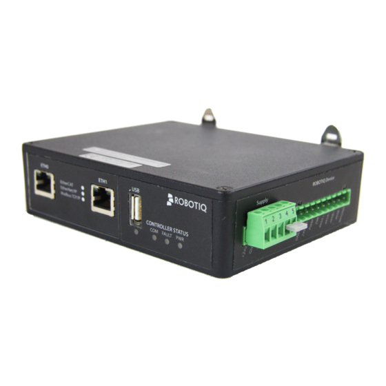
Page 17: Communication Connection
ProfiBUS Modbus RTU The Figure 3.5.2.1 shows the Communication Panel of the Robotiq Universal Controller. The communication port will vary depending on the communication protocol chosen. Real-Time Ethernet family protocols ( Ethernet IP, EtherCAT, Modbus TCP) will come with two (2) RJ45 standard ports. DeviceNet protocol will come with a 5-pin Combicon connector, CANopen with a standard male DB-9 connector, finally ProfiBUS will come with a standard female DB-9 connector. - Page 18 Figure 3.5.2.1 : Representation of the Communication Panel options for the Robotiq Universal Controller. It is the users responsibility to setup the appropriate cable between the Controller unit and the master controller. Robotiq can provide you with appropriate cables available on demand from its Spare Parts, Kits and Accessories section.
-
Page 19: Real-Time Ethernet Communication Protocols
Device Type : Number : Revision 0x00000000 Major Order ID : 1541.110 Number : Revision : Minor Name of nic50repns Revision : station : Device Name AG-EIS Type of Default.Statio station : n.Type Device Access Point Robotiq inc. © 2008 - 2014... - Page 20 Output Data Bytes (16) N / A Bytes : Length : Output Data Cons. Data Module N / A Bytes : Length : Type Byte Count Input Data Bytes (16) Module Type Byte Count Robotiq inc. © 2008 - 2014...
- Page 21 Robotiq Universal Controller Instruction Manual Info EtherCAT protocol uses inherent dynamic addressing, thus bus settings cannot be customized. Info Ethernet/IP uses 4 bytes of header which may be visible or not depending on the master. Robotiq inc. © 2008 - 2014...
-
Page 22: Devicenet Communication Protocol
Robotiq Universal Controller Instruction Manual DeviceNet communication protocol The DeviceNet communication and the Controller use a 24 V power supply. Robotiq suggests to separate power supplies as shown in Figure 3.5.2.2. Caution There is no terminating resistor mounted in the Gripper. - Page 23 Product Type : 0x0000000C Major Revision : Minor Revision : Product Name : AG-DNS BUS SETTINGS MAC ID : Baud Rate : 250 KBaud DATA SETTINGS Prod. Data Length : Cons. Data Length : Robotiq inc. © 2008 - 2014...
-
Page 24: Canopen Communication Protocol
If Gripper is the end of line, then a 120 Ohms resistor must but mounted between pin 4 and 5. Figure 3.5.2.3 : Power connection diagram for the 3-Finger Gripper using CANopen Fieldbus. Robotiq inc. © 2008 - 2014... - Page 25 Baud Rate : 1 MBaud DATA SETTINGS Index Size Send Object 0x2000 Receive Object 0x2200 Output Databytes Input Databytes Hint The CANopen communication interface supports SDO (Service Data Object) and PDO (Process Data Object) protocols. Robotiq inc. © 2008 - 2014...
-
Page 26: Profibus Communication Protocol
Robotiq Universal Controller Instruction Manual PROFIBUS communication protocol PROFIBUS DP (Decentralized Peripheral) is an available option for the Robotiq Universal Controller. Factory settings for PROFIBUS protocol: IDENTIFICATION SETTINGS Model Name NIC 50-DPS Identification Number 0x0C10 Station Address Station address, the address of the device can be set anywhere between 0 and 126. -
Page 27: Control
4.1 Overview The Robotiq Universal Controller is accessed from the robot controller using an industrial protocol (Ethernet/IP, DeviceNet, CANopen, EtherCAT, etc.) and used to operate a Robotiq device. The programming of the Robotiq device can be done with the Teach Pendant of the robot or by offline programming. -
Page 28: Status Leds
Four LED lights provide general information about the Controller and associated device status on the Controller Communication Panel. Figure 4.4.1 shows the LEDs and their locations. Figure 4.4.1 : Controller status LEDs. There is an additional LED on the Robotiq device, see device manual for details. Robotiq inc. © 2008 - 2014... -
Page 29: Supply Led
The following applies to the communication LED on the Controller. Color State Information No network detected Green Blinking A network has been detected, but no connection has been established Green A network has been detected and at least one connection is established Robotiq inc. © 2008 - 2014... -
Page 30: Fault Led
The following applies to the fault LED on the Controller. hint Error code can be obtained reading the Fault Status byte described in section 4.5 Robot Input registers & status or using the Robotiq User Interface menu option ''Input Registers". For the Controller fault LED : Color State Code... -
Page 31: Controller Register Mapping
1 for the functionalities and status registers. Only Byte 2 of Robot Input / Status can be read when no Robotiq devices are present, if one is present, consult the appropriate instruction manual. -
Page 32: Robot Input Registers & Status
Minor Fault ( red LED continuous ) 0x09 - Communication is not ready Major Fault (red LED blinking) – Reset is required 0x0C – Emergency stop triggered 0x0E – Overcurrent protection triggered ( Gripper Robotiq inc. © 2008 - 2014... -
Page 33: User Interface
Robotiq Universal Controller Instruction Manual 5. User Interface Visit http://support.robotiq.com to get the latest installer for the Robotiq User Interface along with appropriate documentation. See the Robotiq User Interface Instruction Manual for details on usage of the RUI. Robotiq inc. © 2008 - 2014... -
Page 34: Specifications
6. Specifications 6.1 Technical dimensions Figure 6.1.1 presents the main technical dimensions of the Robotiq Universal Controller, axis system shown in red represents the coordinate system used to calculate the center of mass and intertia values available in the follow sections. -
Page 35: Mechanical Specifications
Figure 6.3.1. The center of mass and moment of inertia are calculated for a configuration with an Ethernet family option and may vary slightly for other options. Info All values are approximate. Figure 6.3.1 : Approximate value for the moment of inertia and the center of mass for the Universal Controller. Robotiq inc. © 2008 - 2014... -
Page 36: Electrical Ratings
Robotiq Universal Controller Instruction Manual 6.4 Electrical ratings Below are the Electrical ratings for the Robotiq Universal Controller. SPECIFICATION VALUE Operating Supply Voltage 24 V Absolute Maximum Supply Voltage 28 V Quiescent Power (minimum power consumption) 3.6 W Peak Power... -
Page 37: Maintenance
No maintenance is required on the Universal Controller. Note Controller must be kept away from dirty, dust, scraps, chemicals, etc. Always respect the operating conditions. It is a good practice to test emergency stop functionnality when doing Robotiq device maintenance. Robotiq inc. © 2008 - 2014... -
Page 38: Spare Parts, Kits And Accessories
5 m USB 2.0 cable, USB A - A CBL-USB-2057 male. Meant for configuration of the Robotiq Universal Controller communication parameters and control of Robotiq devices via the Robotiq User Interface. Fieldbus cable Available on demand Robotiq inc. © 2008 - 2014... -
Page 39: Troubleshooting
Controller for the Gripper. Other problems If the system shuts down (blue LED goes off) when the Robotiq device activates or grasps an object, check the power supply, the power supply must meet the requirement of your Robotiq device. - Page 40 Controller shuts down or does not power up. Cannot establish a connection (Ethernet family). Cannot establish a connection (CANbus family). Q: Controller and/or associated Robotiq device shuts down when working or does not power up when connected. A: Check the power supply specifications in section 3.3.
-
Page 41: Warranty
Exclusion Robotiq reserves the right to make changes in the design or construction of any of its products at any time without incurring obligation to make any changes whatsoever on units already purchased. -
Page 42: Contact
Go to Contact Us Phone 1-888-ROBOTIQ (762-6847) 1-418-800-0045 (outside US and Canada) 1-418-800-0046 Technical support and Engineering extension 207 Sales US extension 122 Head office Robotiq: 966, chemin Olivier Suite 325 St-Nicolas, Qc G7A 2N1 Canada Robotiq inc. © 2008 - 2014...
Need help?
Do you have a question about the UNI-CTR-001 Series and is the answer not in the manual?
Questions and answers