Table of Contents
Advertisement
Quick Links
Fibaro
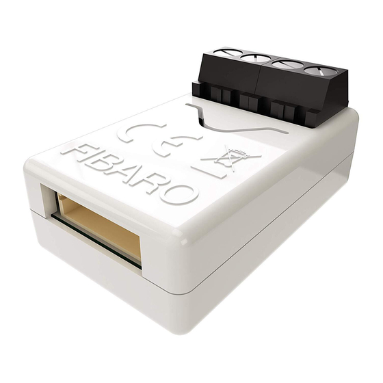
Smart Implant
SKU: FIBEFGBS-222
Quickstart
This is a secure Alarm Sensor for Europe. To run this device please connect it to your mains power supply.
1.Set the main controller in Security S2 Authenticated add mode (see the controllers manual).
2.Scan the DSK QR code or input the 5-digit PIN code (label on the bottom of the box).
3.Power the device.
4.LED will start blinking yellow, wait for the adding process to end.
5.Successful adding will be confirmed by the Z-Wave controllers message.
Important safety information
Please read this manual carefully. Failure to follow the recommendations in this manual may be dangerous or may violate the law. The manufacturer, importer,
distributor and seller shall not be liable for any loss or damage resulting from failure to comply with the instructions in this manual or any other material. Use this
equipment only for its intended purpose. Follow the disposal instructions. Do not dispose of electronic equipment or batteries in a fire or near open heat sources.
What is Z-Wave?
Z-Wave is the international wireless protocol for communication in the Smart Home. This device is suited for use in the region mentioned in the Quickstart section.
Z-Wave ensures a reliable communication by reconfirming every message (two-way communication) and
every mains powered node can act as a repeater for other nodes (meshed network) in case the receiver is
not in direct wireless range of the transmitter.
This device and every other certified Z-Wave device can be used together with any other certified Z-
Wave device regardless of brand and origin as long as both are suited for the same frequency range.
If a device supports secure communication it will communicate with other devices secure as long as this
device provides the same or a higher level of security. Otherwise it will automatically turn into a lower level
of security to maintain backward compatibility.
For more information about Z-Wave technology, devices, white papers etc. please refer to www.z-wave.info.
Product Description
FIBARO Smart Implant allows to enhance the functionality of wired sensors and other devices by adding Z-Wave network communication.You can connect binary
sensors, analog sensors, DS18B20 temperature sensors or DHT22 humidity and temperature sensor to report their readings to the Z-Wave controller.It can also
control devices by opening/closing output contacts independently of the inputs.Main features of FIBARO Smart Implant:- Compatible with any Z-Wave or Z-Wave+
Controller,- Supports Z-Wave network Security Modes: S0 with AES-128 encryption and S2 with PRNG-based encryption,- Allows for connecting sensors: o6
DS18B20 sensors,o1 DHT sensor, o2 2-wire analog sensor, o2 3-wire analog sensor, o2 binary sensors. - Works as a Z-Wave signal repeater,- Built-in
temperature sensor.
Prepare for Installation / Reset
Please read the user manual before installing the product.
In order to include (add) a Z-Wave device to a network it must be in factory default state. Please make sure to reset the device into factory default. You can do
this by performing an Exclusion operation as described below in the manual. Every Z-Wave controller is able to perform this operation however it is recommended
to use the primary controller of the previous network to make sure the very device is excluded properly from this network.
Reset to factory default
This device also allows to be reset without any involvement of a Z-Wave controller. This procedure should only be used when the primary controller is inoperable.
1.Press and hold the button to enter the menu.
2.Release button when the device glows yellow.
3.Quickly click the button to confirm.
4.After few seconds the device will be restarted, which is signalled with the red colour.
Safety Warning for Mains Powered Devices
ATTENTION: only authorized technicians under consideration of the country-specific installation guidelines/norms may do works with mains power. Prior to the
assembly of the product, the voltage network has to be switched off and ensured against re-switching.
Advertisement
Table of Contents

Related Manuals for FIBARO Smart Implant

Summary of Contents for FIBARO Smart Implant
- Page 1 Product Description FIBARO Smart Implant allows to enhance the functionality of wired sensors and other devices by adding Z-Wave network communication.You can connect binary sensors, analog sensors, DS18B20 temperature sensors or DHT22 humidity and temperature sensor to report their readings to the Z-Wave controller.It can also control devices by opening/closing output contacts independently of the inputs.Main features of FIBARO Smart Implant:- Compatible with any Z-Wave or Z-Wave+...
-
Page 2: Installation
Installation Connect only in accordance with one of the diagrams, The device is powered with secure voltage; nevertheless, the user should be extra careful or should commission the installation to a qualified person, Do not connect devices which are not compliant with the specification, Do not connect other sensors than DS18B20 or DHT22 to SP and SD terminals, Do not connect sensors to SP and SD terminals with wires longer than 3 meters, Do not load the device outputs with a current exceeding 150mA,... - Page 3 3. Verify correctness of connection. 4. Power the device. 5. Add the device to the Z-Wave network. Connection with DHT22 The DHT22 sensor may easily be installed wherever humidity and temperature measurements are required. You can connect only 1 DHT22 sensor to TP-TD terminals. 1.
- Page 4 You can connect up to 2 analog sensors IN1/IN2 terminals. 1. Disconnect Power 2. Connect with the diagram below 3. Verify the correctness of connection. 4. Power the device. 5. Add the device to the Z-Wave network. 6. Change values of parameters: Connected to IN1: change parameter 20 to 4 Connected to IN2: change parameter 21 to 4 Connection with binary sensor or button...
-
Page 5: Product Usage
Connection with gate opener Smart Implant can be connected to different devices to control them. In this example it is connected to gate opener with impulse input (every impulse will start and stop the gate motor, alternately opening/closing). 1. Disconnect Power 2. - Page 6 ANT (black) - antenna GND (blue) - ground conductor SD (white) - signal conductor for DS18B20 or DHT22 sensor SP (brown) - power supply conductor for DS18B20 or DHT22 sensor (3.3V) IN2 (green) - input no. 2 IN1 (yellow) - input no. 1 GND (blue) - ground conductor P (red) - power supply conductor OUT1 - output no.
-
Page 7: Quick Troubleshooting
The wakeup interval is a tradeoff between maximal battery life time and the desired responses of the device. To wakeup the device please perform the following action: FIBARO Smart Implant is powered using DC power supply unit so it is always awake. -
Page 8: Configuration Parameters
Maximum Group Number Description Nodes Lifeline reports the device status and allows for assigning single device only (main controller by default). On/Off (IN1) is assigned to IN1 input terminal (uses Basic command class). On/Off (IN2) is assigned to IN2 input terminal (uses Basic command class). Configuration Parameters Z-Wave products are supposed to work out of the box after inclusion, however certain configuration can adapt the function better to user needs or unlock further enhanced features. - Page 9 Setting Description Key pressed 1 time Key pressed 2 times Key pressed 3 times Key hold down and key released Parameter 41: Input 2 - sent scenes This parameter defines which actions result in sending scene ID and attribute assigned to them (see 9: Activating scenes). Parameter is relevant only if parameter 20 is set to 2 or 3.
- Page 10 This parameter defines minimal change (from the last reported) of internal temperature sensor value that results in sending new report. Size: 2 Byte, Default Value: 5 Setting Description reporting on change disabled 1 - 255 (0.1-25.5C) Parameter 66: Internal temperature sensor - periodical reports This parameter defines reporting period of internal temperature sensor value.
-
Page 11: Technical Data
Parameter 154: Output 1 - logic of operation This parameter defines logic of OUT1 output operation. Size: 1 Byte, Default Value: 0 Setting Description contacts normally open / closed when active contacts normally closed / open when active Parameter 155: Output 2 - logic of operation This parameter defines logic of OUT2 output operation. -
Page 12: Explanation Of Z-Wave Specific Terms
Association V2 Basic Central Scene V3 Configuration Crc 16 Encap Device Reset Locally Firmware Update Md V4 Manufacturer Specific V2 Multi Channel Association V3 Multi Channel V4 Notification V8 Powerlevel Protection V2 Security Security 2 Sensor Multilevel V11 Supervision Switch Binary Transport Service V2 Version V2 Zwaveplus Info V2...
Need help?
Do you have a question about the Smart Implant and is the answer not in the manual?
Questions and answers