Table of Contents
Advertisement
Advertisement
Table of Contents

Subscribe to Our Youtube Channel
Related Manuals for Muirhead 9252

Summary of Contents for Muirhead 9252
- Page 1 PRODUCT MANUAL PROGRAMMABLE LUBRICATION CONTROLLER Part No. 9252...
- Page 2 DISCLAIMER © Remote Control Technologies Pty Ltd. ■ No part of this manual may be reproduced, copied, translated, or transmitted in any form or by any means without the written permission of RCT. ■ Information provided in this manual is intended to be accurate and reliable. However, RCT assumes no responsibility for its use or infringements upon the rights of third parties that may result from its use.
-
Page 3: Table Of Contents
Contents General Safety Warnings Personal Safety Machine Product Product Overview Features and Functions Operation and Use Control Unit Inputs Outputs LED Indication Software Options Installation Guide Wiring Connections Wiring Connections for part number 4606 and 3560 Wiring Diagrams − Single Bank System – External Wiring Diagram (427i) −... - Page 4 Compliance and Standards Troubleshooting Glossary Warranty Revision History 4 | 28 M0588.docx | Rev 1.5 | Modified on 12/11/2018 | © Remote Control Technologies Pty Ltd...
- Page 5 Table of Figures Figure 1 Programmable lubrication controller ....................7 Figure 2 Drawing 427i Single bank system external wiring diagram .............. 11 Figure 3 Drawing 427h Dual bank system external wiring diagram ............... 12 Figure 4 Drawing 427j Basic programming adaptor lead external wiring diagram ......... 13 Figure 5 Drawing 423a –...
-
Page 6: General Safety Warnings
General Safety Warnings Personal Safety ■ Everyone is responsible for safety. ■ The installer/service personnel should be trained and authorized to complete the required work. ■ Ensure that the machine is safely isolated during installation and testing to protect all personnel. ■... -
Page 7: Product Overview
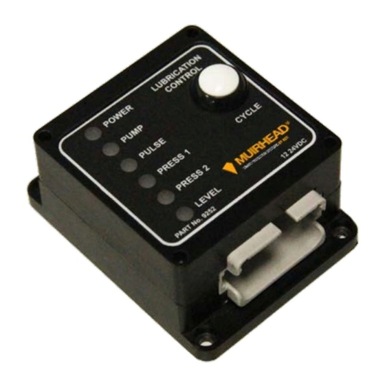
® The Muirhead Programmable Lubrication Controller, part number 9252, is designed for flexibility and is used to automate the grease injection system on a machine. The programmable lubrication (lube) controller is capable of operating in many different modes to suit multiple lubrication systems available on the market. -
Page 8: Operation And Use
Operation and Use The Muirhead ® Programmable Lubrication Controller has been designed with flexibility in mind. The system is capable of operating in many different modes which suit multiple lubrication systems. Control Unit The lube controller has been designed to be an in-cabin mounted device. -
Page 9: Outputs
Outputs Pump output This connection is a positive switching FET output. Rated up to 8 A, this output is used to operate the lube pump. The active time period for this output is software configurable. Pulse output This connection is a positive switching FET output. Rated up to 8 A, this output is used to control a pulsing circuit to drive a reciprocating pump. -
Page 10: Installation Guide
Not Used Not used There will be extra features when installing the 9252 please refer to the manual for connection details on these. 10 | 28 M0588.docx | Rev 1.5 | Modified on 12/11/2018 | © Remote Control Technologies Pty Ltd... -
Page 11: Wiring Diagrams
Wiring Diagrams Single Bank System – External Wiring Diagram (427i) Figure 2 Drawing 427i Single bank system external wiring diagram 11 | 28 M0588.docx | Rev 1.5 | Modified on 12/11/2018 | © Remote Control Technologies Pty Ltd... -
Page 12: Dual Bank System - External Wiring Diagram (427H)
Dual Bank System – External Wiring Diagram (427h) Figure 3 Drawing 427h Dual bank system external wiring diagram 12 | 28 M0588.docx | Rev 1.5 | Modified on 12/11/2018 | © Remote Control Technologies Pty Ltd... -
Page 13: Basic Programming Adaptor Lead - External Wiring Diagram (427J)
Basic Programming Adaptor Lead – External Wiring Diagram (427j) Figure 4 Drawing 427j Basic programming adaptor lead external wiring diagram 13 | 28 M0588.docx | Rev 1.5 | Modified on 12/11/2018 | © Remote Control Technologies Pty Ltd... -
Page 14: In-Line Programming Adaptor Lead - Loom Configuration (423A)
In-Line Programming Adaptor Lead – Loom Configuration (423a) Figure 5 Drawing 423a – In-line programming adaptor lead loom configuration 14 | 28 M0588.docx | Rev 1.5 | Modified on 12/11/2018 | © Remote Control Technologies Pty Ltd... -
Page 15: Calibration
The following part numbers are required when programming the lube controller: Part No. Item 11199 Kit Programming Lube Controller (part number 9252) 2694 Adaptor, USB-to-Serial This software is a single executable (.exe) file and can be launched by double-clicking its icon. -
Page 16: Connecting Via Com Port
Upgrading the Device ® If the version of firmware inside the device is out-of-date, then the Muirhead Device Tool software will detect this when a connection is first made, and the software will display a request to update the firmware. Click Yes, and the software will proceed to load the new firmware and will display the updating progress on a status bar. -
Page 17: Section 1 - Tabbed Browsing Of Devices
Section 1 – Tabbed Browsing of Devices Each lube controller that you connect or simulate through the software is displayed in a tab. You can easily switch between devices by selecting the tab of the required device. Clicking the small tab with the gear symbol icon will display the home screen to enable connection of or simulate another lube controller. -
Page 18: Section 3 - Inputs Section
Section 3 – Inputs Section The inputs section allows for the configuration of inputs for the operation of the unit. The inputs section is always on the left-hand side of the screen. Refer to Figure 8, section 3 in this document. Inputs can be configured to allow for various sensors and switching configurations to cater for a multitude of machines with differing input sensors or devices. -
Page 19: Figure 12 Options Section For A Lube Controller
Options The options in the options section directly below the inputs section affect how the device behaves. Figure 12 Options section for a lube controller Option Description Lockout Pump When enabled, the lubrication pump is locked out after an open failure. Manual Cycles lubrication cycles are permitted when the lubrication pump has been locked out. -
Page 20: Section 4 - System State
Section 4 – System State The system state section (Figure 8, section 4) displays the device information, diagnostics, counters and device configurations. The system state section is always the centre column of the screen. Device Information Device information consists of fields which can be edited to record details relating to the setup and installation of the device. - Page 21 Timer Description Bank 1 Active Time that bank 1 is active during a lubrication cycle (default: two minutes). Bank 2 Active Time that bank 2 is active during a lubrication cycle (only applicable when 2 lube banks enabled) (default: two minutes). Bank 2 Skip Number of lube cycles that bank 2 is inactive for (i.e., skipped) (default: 0).
-
Page 22: Section 5 - Outputs/Indicators
Section 5 – Outputs/Indicators The output/indicators section (Figure 8, section 5) allows for the configuration of outputs as well as options for the operation of the outputs. The output/indicators section is always on the right-hand side of the screen. Outputs can be configured to suit the requirements of the devices that they are required to drive. Layout of Outputs Section The output set-up options are listed in the output section. -
Page 23: Testing And Simulation
® When running a simulation, the Muirhead Lube Controller software automatically overrides all inputs. Then the user must control the inputs to the desired states. The lube controller software will simulate how the lube controller would operate out in the field. -
Page 24: Factory Default Settings
Factory Default Settings Lubrication Options Lubrication bank configuration Single Pump output type Continuous and pulsed Pressure sensors fitted Lube on power up Externally mounted lubrication button Timer Settings Pause time 15 minutes Lubrication time 2 minutes Alarm Options Low grease level alarm Continuous Alarm mute period 10 minutes... -
Page 25: Parts List
The following table lists parts that are supplied with the programmable lubrication (lube) controller. Part No. Description 9252 Programmable Lube Controller The following parts are required when programming the 9252 lube controller. The kits listed below are not included with the lube controller and must be purchased separately. Part No. Description 11199 Kit Programming Lube Controller (9252) ■... - Page 26 Glossary Amp (Ampere) Minimum alternating current millimetres Advanced Management System Milliwatts Auxiliary Output Not Applicable Controller Area Network Normally Closed ® CMIO ControlMaster Input Output PCB Normally Open ® ControlMaster Receiver Original Equipment Manufacturer ® ControlMaster Transmitter Outputs ® CM2200 ControlMaster 2200 Remote Set Output...
- Page 27 Revision History Date Details of change 08/07/2011 Initial document draft and approval 12/10/2015 Updated Operation and Use, Installation Guide and Calibration sections 25/10/2016 Updated Company Contact information. 27/03/2018 JunW Updated all screenshots. 05/04/2018 JunW Updated drawing 423a 12/11/2018 Updated manual format – added Revision History section. 27 | 28 M0588.docx | Rev 1.5 | Modified on 12/11/2018 | ©...
- Page 28 Discover more: www.rct-global.com sales@rct-global.com AUSTRALIA: +61 (0) 8 9353 6577 AFRICA: +27 (0) 83 292 4246 CANADA: +1 705 590 4001 RUSSIA / CIS: +7 (910) 411 11-74 SOUTH AMERICA: +56 9 3417 0004 USA: +1 801 938 9214...
Need help?
Do you have a question about the 9252 and is the answer not in the manual?
Questions and answers