
Related Manuals for Daiichi Electronics SQLC-110L


Summary of Contents for Daiichi Electronics SQLC-110L
- Page 1 SQLC-214-097 INSTRUCTION MANUAL Power Line Super Multi-Meter SQLC-110L [ 1φ2W / 1φ3W / 3φ3W Analog Output ] Hardware Model F...
- Page 2 SQLC-214-097 Introduction Thank you for your purchase of our product. Read this instruction manual carefully before installation, wiring, and using this product. Keep this instruction manual handy for reference at any time. Have a contact with us or sales agent in case that this instruction manual is lost or damaged. <Caution>...
- Page 3 SQLC-214-097 Cautions on safety Cautions on safe use 1. Working and storage environments Don’t mount or store this unit in the following environments. If the unit becomes defective due to the use in an environment other than specified, it may be repaired for pay even during its warranty period (one year after the date of delivery).
- Page 4 SQLC-214-097 5. Setting This unit requires setting and confirmation of the measuring range, etc. before use. Wrong setting, if any, causes malfunction of the unit. If setting should be wrong, neither measurement nor output becomes correct. Carefully read the instruction manual before setting the unit. ...
- Page 5 SQLC-214-097 ① Voltage, current input (2/2) 3-phase 3-wire Single-phase № Setting item Single-phase 3-wire 110V input 220V input 110V input 220V input Voltage range 6600V 220V 110.0V 3300V 220V Current range 100.0A 500A 50.0A Current display peculiar 100.0A 500A 50.0A sensitivity Measurement range Active power polarity...
- Page 6 SQLC-214-097 ② Current input № Setting item 3-phase 3-wire Single-phase 3-wire Single-phase Pattern Pattern 15 Pattern 15 Pattern 15 Main monitor A(V) A(U) Sub-monitor (Left) A(U) A(W) - Display combination Sub-monitor (Center) A(W) A(N) - Sub-monitor (Right) - - - Bar graph A(V) A(U)
- Page 7 SQLC-214-097 ③ Voltage input 3-phase 3-wire Single-phase № Setting item Single-phase 3-wire 110V input 220V input 110V input 220V input Pattern Pattern 16 Pattern 16 Pattern 16 Main monitor V(UV) V(UN) Sub-monitor (Left) V(VW) V(WN) - Display combination Sub-monitor (Center) V(WU) V(UW) -...
- Page 8 SQLC-214-097 6. Operation Be careful with the following cautions during use. Use the input within the rated range. Be careful since negligence of this caution may cause troubles of the unit. There is a function to hold the maximum value and the minimum value with a measurement factor in this product. A blackout is guaranteed and this value isn't also cleared by a power supply reset.
-
Page 9: Table Of Contents
SQLC-214-097 Content 1. Product outline ・・・・・・・・・・・・・・・・・・・・・・・・・・・・・・・・・・・・・・・・・・・・・・・・・・・・・・・・・・・・・・・ 9 1.1 Usage of product ・・・・・・・・・・・・・・・・・・・・・・・・・・・・・・・・・・・・・・・・・・・・・・・・・・・・・・・・・・・ 9 1.2 Features of product ・・・・・・・・・・・・・・・・・・・・・・・・・・・・・・・・・・・・・・・・・・・・・・・・・・・・・・・・ 9 2. The name and function of each part ・・・・・・・・・・・・・・・・・・・・・・・・・・・・・・・・・・・・・・・・・・・・ 10 3. Preparation 3.1 Installation ・・・・・・・・・・・・・・・・・・・・・・・・・・・・・・・・・・・・・・・・・・・・・・・・・・・・・・・・・・・・・・・ 10 3.2 Connections ・・・・・・・・・・・・・・・・・・・・・・・・・・・・・・・・・・・・・・・・・・・・・・・・・・・・・・・・・・・・・・・・ 12 4. Operation ・・・・・・・・・・・・・・・・・・・・・・・・・・・・・・・・・・・・・・・・・・・・・・・・・・・・・・・・・・・・・・・・・・・・・ 17 4.1 The screen change and function by switch operation ・・・・・・・・・・・・・・・・・・・・・・・・・... -
Page 10: Product Outline
SQLC-214-097 1. Product outline 1.1 Usage of product This single unit can measure and monitor demand-current ×3, voltage ×3, current ×3, demand active power, active-power, reactive-power, power-factor, frequency, watt-hour, var-hour, harmonic(voltage, current) and current leakage. From a low tension circuit to a high tension circuit, it is adapted for various usages, such as a measurement monitor of a power-receiving circuit, an energy conservation power monitor, a demand current measurement monitor, and a harmonic monitor, a leakage monitor. -
Page 11: The Name And Function Of Each Part
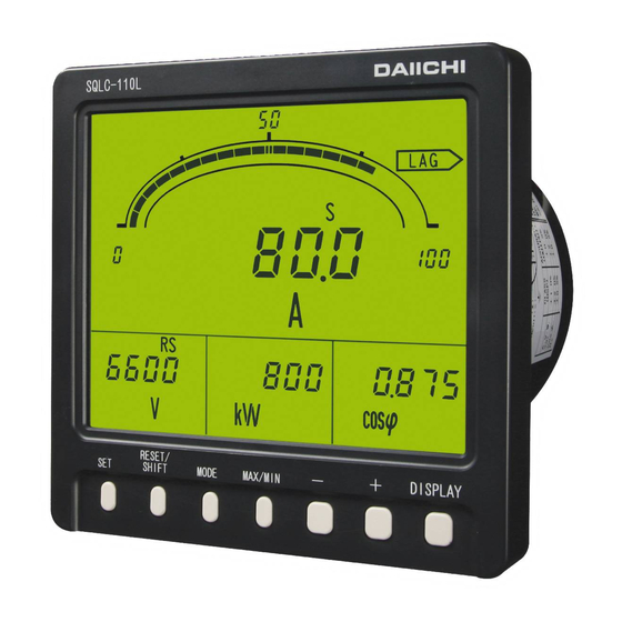
SQLC-214-097 2. The name and function of each part Bar graph display Scale markings The measurement value of the main monitor Scale markings is automatically set in a is indicated by the analog. measurement range. (Setting which does bar graph display Upper limit (or lower limit) setting index of the measurement value of sub-monitor An upper limit (or lower limit) set point... - Page 12 SQLC-214-097 (2) Correspondence ZCT (Our company recommendation) ZCT is not attached with leakage measurement. 50A OTG-LA21 (OMRON Corporation) 100A OTG-LA30 (OMRON Corporation) 200A OTG-LA42 (OMRON Corporation) 400A OTG-LA68 (OMRON Corporation) 600A OTG-LA82 (OMRON Corporation) 100A(For outdoor) OTG-LA30W (OMRON Corporation) * Installation pitch This product also corresponds to the next ZCT.
-
Page 13: Connections
SQLC-214-097 ● Installation (1) A product is put in a cut hole of a panel from a front. A body is inserted until it exceeds retaining stopper of the lower base. (2) Please fix a product certainly with attached M5 flange nut for installation. - Page 14 SQLC-214-097 (5) Current input 3φ3W (2CT) (6) Current input 3φ3W (3CT) AUX.SUPPLY AUX.SUPPLY LOAD ANALOG OUTPUT1 ANALOG OUTPUT1 LOAD ANALOG OUTPUT2 ANALOG OUTPUT2 ANALOG OUTPUT3 ANALOG OUTPUT3 ANALOG OUTPUT4 ANALOG OUTPUT4 CONTACT OUTPUT1 CONTACT OUTPUT1 CONTACT OUTPUT2 CONTACT OUTPUT2 ( ) EXT.INPUT1 EXT.INPUT1 EXT.INPUT2 EXT.INPUT2...
- Page 15 SQLC-214-097 ● Schematics in the leakage monitor of low-voltage circuit ( (1) 1φ2W (N-phase earth) (2) 1φ3W (N-phase earth) AUX.SUPPLY AUX.SUPPLY ANALOG OUTPUT1 ANALOG OUTPUT1 ANALOG OUTPUT2 ANALOG OUTPUT2 ANALOG OUTPUT3 ANALOG OUTPUT3 ANALOG OUTPUT4 ANALOG OUTPUT4 CONTACT OUTPUT1 CONTACT OUTPUT1 CONTACT OUTPUT2 CONTACT OUTPUT2 LOAD...
- Page 16 SQLC-214-097 ● In case of installing ZCT to ground wire by leakage monitor. W (1φ3W, N-phase grounding) W (3φ3W, V-phase grounding) LOAD <Caution> When doing Igr measurement by a leakage monitor, please be careful about polarity of ZCT. ● Caution on connection (1) Mount the terminal cover without fail for safety after the end of connections.
- Page 17 SQLC-214-097 ● The distinction method of the primary side polarity of ZCT (1) Product of OMRON Corporation The direction (near side) which can read correctly the character of the name plate currently stuck on ZCT is "K". (2) Product of TAIWA ELECTRIC INDUSTRIES CO.,LTD. ①...
-
Page 18: Operation
SQLC-214-097 4. Operation ● The function of switch Switch Function The integrated value of electric energy is changed to the usual display and an enlarged display. If it continues pushing 3 seconds or more, it will change to setting mode. In setting mode, it is used for the determination of a set point. -
Page 19: The Screen Change And Function By Switch Operation
SQLC-214-097 4.1 The screen change and function by switch operation This product changes various screens by switch operation. Here, the change step of the screen by switch operation is explained. Display mode DISPLAY Instant measurement display RESET/ Phase (line) SHIFT Electric-energy display change General... -
Page 20: The Kind Of Display
SQLC-214-097 4.2 The kind of display 4.2.1 Measurement display A measurement value display has the three following types of displays. The change of the measurement display element of the main monitor by switch operation and the change of the phase / line display of current / voltage is possible (temporarily). In a general measurement display, if switch operation is not performed for 10 minutes after changing a display element, it returns to the original measurement display element automatically. - Page 21 SQLC-214-097 Measurement Measurement Example of display Note Example of display Note factor factor Reactive Power factor power LEAD LEAD display display var-hour var-hour “LAG” “LEAD” (Power (Power receiving, display receiving, display LAG) LEAD) var-hour var-hour “LAG” and (Power “LEAD” and ” (Power ”-”...
- Page 22 SQLC-214-097 ③ Voltage harmonic measurement display It is a measurement factor display of the distortion factor of voltage, relative harmonic content, harmonic effective value, etc. About a function, it is the same as a current harmonic measurement display. Distortion-factor maximum Effective-value maximum Distortion-factor display Effective-value display...
-
Page 23: Alarm Detection Display
SQLC-214-097 4.2.2 Alarm detection display The alarm value setting is a possible measurement factor (demand current and harmonic, etc.), it displays in case an input exceeds a set point. Besides the usual measurement display, the detected factor is displayed on a screen upper case. In addition, in case setting OFF (not use) as measurement factor, it does not detect. - Page 24 SQLC-214-097 Alarm factor Example of a display Alarm factor Example of a display Voltage Upper Upper harmonic Demand limit limit Detection display content Alarm setting value Alarm setting Detection Value display Setting as 11th content of bar graph (Distinguishes in an underbar) Upper Voltage Upper...
-
Page 25: Setting Display
SQLC-214-097 Alarm factor Example of a display Current Upper distortio limit n factor Detection display Alarm setting value 4.2.3 Setting display It is the display at the case of various setting. There are three types of setting modes according to the contents of a setting. -
Page 26: Operation
SQLC-214-097 4.3 Operation 4.3.1 The main monitor display-element change The measurement display element of the main monitor is changed. A change is performed by + -. This operation can be performed also except a general measurement display (harmonic measurement display, maximum display and minimum display). -
Page 27: Harmonic Measurement Display Change
SQLC-214-097 4.3.3 Harmonic measurement display change A general measurement display and a harmonic measurement display are changed. A change is performed by MODE . Whenever it pushes a switch, it changes as follows. General measurement display → Current harmonic measurement display →... -
Page 28: Setting Value Check
SQLC-214-097 4.3.5 Setting value check A voltage range (VT ratio), a current range (CT ratio), and an alarm-output set point are checked. Check is RESET/SHIFT and - are pushed simultaneously and performed. The change of a set point is carries out by + and - . This operation can be performed also except a general measurement display (harmonic measurement display, maximum display and minimum display). -
Page 29: Setting Mode
SQLC-214-097 4.3.6 Setting mode Various kinds of setting are performed. Setting mode is three types, and operations are different. DISPLAY is pushed in case it returns to the original measurement display. And, if a switch is not operated for 10 minute after a set point check, it will return to the original measurement display automatically. Operation and the contents of setting (detail) in setting mode, please refer to "5 Setting". -
Page 30: Reset
SQLC-214-097 4.3.7 Reset Various kinds of reset are performed. The kind of reset is as follows and operations are different, respectively. Reset of watt-hour integrated value (zero clear), Reset of maximum value and minimum value (it updates to the instantaneous value at the time), Alarm-output reset (OFF of an alarm output (at the case of manual reset setting)). - Page 31 SQLC-214-097 (2) Reset of maximum value and minimum value Reset of the various measurement values of maximum value and minimum value is performed. This reset has two types of methods. (How to perform according to a measurement factor individual. How to reset all maximum values and minimum values by package.) a) Individual reset Reset of only a certain differential maximum value or the minimum value is performed.
- Page 32 SQLC-214-097 (3) Alarm reset In case an alarm return method is set to “HOLD (manual return)”, an alarm output is reset (output OFF). (With an alarm-output option) However, an output is not turned off by this operation, in case an alarm continues and it has caused. And, this operation is unnecessary in case setting as "AUTO (automatic return)”...
-
Page 33: Setting
SQLC-214-097 5. Setting < Caution > When changing the input circuit setting, please be sure to perform a setup from an input circuit setting in the setting mode 3. After changing the other setting, when the input circuit setting is changed the set value returns to default value (default value of a changed input circuit). - Page 34 SQLC-214-097 Setting mode 1. Function table (2) Current Voltage Important Setting Function Functional description Default setting Page input input setting Demand active power Set the time interval of demand active 0 second ○ 53,54 time interval power. Operating system Demand active power Set the operating method of demand according with ○...
- Page 35 SQLC-214-097 Setting mode 2. Function table (1) Important Setting Current Voltage Function Functional description Default setting Page input input setting 3φ3W 6600V ( Set the voltage-measurement range Voltage range ○ 1φ3W 110.0V ○ 58-60 (VT ratio). 1φ2W 3300V ( 3φ3W 100.0A Set the current-measurement range Current range...
- Page 36 SQLC-214-097 Setting mode 2. Function table (2) Important Setting Current Voltage Function Functional description Default setting Page input input setting 241P Set the output factor of PO1 (pulse PO1 factor ○ output 1). 3φ3W 10kWh/p 242P Set the output pulse unit of PO1 PO1 pulse unit 1φ3W (pulse output 1).
- Page 37 SQLC-214-097 Setting mode 3. Function table Important Setting Current Voltage Function Functional description Default setting Page input input setting 3φ3W 3φ3W Input circuit phase 1φ3W Set the input circuit or phase line. ○ ○ 1φ3W ○ line change (U-N-W) 1φ2W 1φ2W 3φ3W 110V...
-
Page 38: Setting Table
SQLC-214-097 5.2 Setting table A setting item changes by the specification of a product, or the existence of an option. (1) Important setting Each parenthesized number shows a setting number and this number is displayed on the setting screen. Items Setting and operation procedures Page Press SET and RESET/SHIFT together for longer than 3 seconds... - Page 39 SQLC-214-097 Items Setting and operation procedures Page Press SET for longer than 3 seconds Press MODE (111) (121AL) Set the factor of Select an output factor by + and - Press SET Selected factor is entered alarm output 1. (121AL) Press DISPLAY Returns to display mode.
- Page 40 SQLC-214-097 (2) A combination except a display pattern. Each parenthesized number shows a setting number and this number is displayed on the setting screen. Items Setting and operation procedures Page Press SET for longer than 3 seconds Press RESET/SHIFT Set the display (111) (112) factor of main...
- Page 41 SQLC-214-097 (4) Setting of reactive power measurement range. Each parenthesized number shows a setting number and this number is displayed on the setting screen. Items Setting and operation procedures Page Press SET and RESET/SHIFT together for longer than 3 seconds Press RESET/SHIFT (211) (212)
- Page 42 SQLC-214-097 (8) Setting of analog output. Each parenthesized number shows a setting number and this number is displayed on the setting screen. Items Setting and operation procedures Page Press SET and RESET/SHIFT together for longer than 3 seconds Press MODE (211) (221A) Set the analog...
- Page 43 SQLC-214-097 (9) Setting of alarm output. Each parenthesized number shows a setting number and this number is displayed on the setting screen. Items Setting and operation procedures Page Press SET for longer than 3 seconds Press MODE Press RESET/SHIFT Set the return (111) (121AL) (122AL)
- Page 44 SQLC-214-097 (11) Harmonic measurement setting Each parenthesized number shows a setting number and this number is displayed on the setting screen. Items Setting and operation procedures Page Press SET for longer than 3 seconds Press MODE Press MODE Press MODE Set the high-alarm (111) (121AL)
- Page 45 SQLC-214-097 Items Setting and operation procedures Page Press SET for longer than 3 seconds Press MODE Press MODE Press MODE (111) (121AL) (131H) (141H) Press RESET/SHIFT Press RESET/SHIFT Press RESET/SHIFT Press RESET/SHIFT Set the detected (142H) (143) (144H) (145H) characteristics of Press RESET/SHIFT Press RESET/SHIFT Press RESET/SHIFT...
- Page 46 SQLC-214-097 Items Setting and operation procedures Page Press SET for longer than 3 seconds Press MODE Press MODE Press MODE (111) (121AL) (131H) (141H) Set the leakage Press MODE Press MODE Press RESET/SHIFT Press RESET/SHIFT detected circuit configuration. (151H) (161) (162) (163) (by 3-phase 3-wire)
-
Page 47: Setting In Detail Explanation
SQLC-214-097 5.3 Setting in detail explanation 5.3.1 Setting mode 1 3 seconds 111 to 116 DISPLAY Display setting MODE 121AL to 128AL DISPLAY Alarm output setting MODE 131H to 136 DISPLAY Demand detection setting MODE Display mode 141H to 14A DISPLAY (Measurement Harmonic detection setting... - Page 48 SQLC-214-097 (1) 111 to 116 Display combination setting 【All models】 ● 3-phase 3-wire (Voltage, current input) ( Sub-monitor Sub-monitor Sub-monitor № Pattern № Main monitor Bar graph (Left) (Center) (Right) Pattern 1 A(V) V(UV) A(V) Pattern 2 A(V) V(UV) cosφ A(V) Pattern 3 A(V)
- Page 49 SQLC-214-097 ● Single-phase 3-wire (Voltage, current input) ( Sub-monitor Sub-monitor Sub-monitor № Pattern № Main monitor Bar graph (Left) (Center) (Right) Pattern 1 A(U) V(UN) A(U) Pattern 2 A(U) V(UN) cosφ A(U) Pattern 3 A(U) V(UN) A(U) Pattern 4 DA(U) A(U) V(UN) DA(U)
- Page 50 SQLC-214-097 ● Single-phase 2-wire (Voltage, current input) ( Sub-monitor Sub-monitor Sub-monitor № Pattern № Main monitor Bar graph (Left) (Center) (Right) Pattern 1 Pattern 2 cosφ Pattern 3 Pattern 4 Pattern 5 Pattern 6 cosφ Pattern 7 Pattern 8 cosφ Pattern 9 Pattern 10 Pattern 11...
- Page 51 SQLC-214-097 Display combination setting RESET/SHIFT RESET/ RESET/ RESET/ RESET/ RESET/ Combination Sub-monitor Sub-monitor Sub-monitor Bar graph Main monitor SHIFT SHIFT SHIFT SHIFT SHIFT display (Left) (Center) (Right) factor Pattern 1 A(V):5 V(UV):1 Wh:14 Main monitor W:10 + - + - +...
- Page 52 SQLC-214-097 ◆ 111 Combination display Setting № New setting Select the factors to be measured and monitored by 4 digital Current setting displays out of combination patterns. Set values are updated by SET . ◆ 112 to 115 Main monitor, Sub-monitor (left), Sub-monitor (center), Sub-monitor (right) Set these items for a display configuration other than combined patterns.
- Page 53 SQLC-214-097 (2) 121AL to 128AL Alarm output setting 【With an alarm output option】 Various setting and an output test are performed about an alarm output. In case contact outputs 1 and 2 are alarm-output specifications, the corresponding alarm output is setting. 122AL 123AL 121AL...
- Page 54 SQLC-214-097 (3) 131H to 136 Demand detection setting 【Except voltage input】 The following operation method is setting. Demand current, action of demand, high-alarm value, time-interval, power-factor, demand active power. 133H 131H RESET/ RESET/ Demand power Demand current Demand current SHIFT SHIFT upper limit upper limit...
- Page 55 SQLC-214-097 ◆ 136 Power-factor operation method The operation method of power-factor measurement can be selected from 0 (instant measurement) and 1 (averaging operator in a demand time interval). In case it is set as "1 (averaging operator in a demand time interval)", power-factor measurement is calculated from the operation method of a power demand time interval and a demand active power meter.
- Page 56 SQLC-214-097 ◆ 149 5th conversion detection characteristics. The detection characteristics of 5th conversion content can Alarm output, Inverse-time-delay characteristics be selected from A (average mode) and I (inverse-time-delay In case of high-limit-setting value 35% mode). (voltmeter 3.5%) 10000 In case of "A (average mode)", when average measured value (the average of instantaneous value in average time interval) exceeded the upper limit alarm value, it detects.
- Page 57 SQLC-214-097 (6) 161 to 164 Leakage detection setting 【With leakage measurement】 The rated sensitivity current value of leakage measurement, a detection factor, the circuit configuration at the case of 3-phase 3-wire, and setting of ZCT to be used are performed. Leakage detection RESET/ RESET/...
- Page 58 SQLC-214-097 (7) 171 to 172 Backlight setting 【All models】 (However, the brightness of backlight is only white backlight products) It sets action and brightness of backlight. RESET/ RESET/ Backlight action SHIFT Backlight brightness SHIFT New setting Current setting ◆ 171 Backlight action It can select from ON (always-on), AUTO (auto off), and OFF (always-off) about action of backlight.
-
Page 59: Setting Mode 2
SQLC-214-097 5.3.2 Setting mode 2 SET and RESET/SHIFT 3 seconds 211 to 218 DISPLAY Measurement-range setting MODE 221A to 228A DISPLAY Analog output setting MODE 241P to 244P DISPLAY Pulse output setting Display mode MODE (Measurement display) 251 to 252 DISPLAY External operation input setting MODE... - Page 60 SQLC-214-097 ◆ 211 Voltage range Set the voltage range (VT ratio). Change of this setting also sets the measurement range of active power and reactive power automatically simultaneously. Selection by + and - , set value is updated by SET . Default setting:6600V(3φ3W)、110.0V(1φ3W)、3300V(1φ2W) Voltage measurement range (34 range) Setting factor...
- Page 61 SQLC-214-097 ◆ 214 Active power polarity A swing display of active power meter can be selected from P (one side swing) and - (both swings). Selection by + and - , set value is updated by SET . Default setting:P (One-side swing) New setting +...
- Page 62 SQLC-214-097 (2) 221A to 228A Analog output setting 【With an analog output option】 Various setting of analog output is performed. New setting 221A 222A 223A 224A Setting No. Current setting RESET/ RESET/ RESET/ Ao1 output Ao2 output Ao3 output Ao4 output SHIFT SHIFT SHIFT...
- Page 63 SQLC-214-097 Current setting ◆ 225A Current output intrinsic sensitivity, Setting No. New setting 226A Active power output intrinsic sensitivity, 227A Reactive power output intrinsic sensitivity. Output intrinsic sensitivity (% of an output to an input) is set about each analog output of current, active power, and reactive power. The setting range can be selected from the following.
- Page 64 SQLC-214-097 (4) 251 to 252 External operation input setting 【With an external operation input option】 Various setting of external operation input is performed. Setting factor New setting RESET/ External operation External operation SHIFT input 1 function input 2 function ALARM and RESET are RESET/ displayed by turns.
- Page 65 SQLC-214-097 (5) 261 to 26D Measurement ON/OFF setting 【All models (However, a current leakage is with leakage measurement)】 Measurement display ON/OFF setting of each measurement factor is performed. Selection by + and - , set value is updated by SET . Default setting:ON (All measurement factors) New setting Setting No.
-
Page 66: Setting Mode 3
SQLC-214-097 5.3.3 Setting mode 3 SET and DISPLAY 3 seconds 311 to 312 DISPLAY Input circuit setting MODE 321 to 322 DISPLAY Measurement setting Display mode MODE (Measurement display) DISPLAY Analog output specification change MODE 341 to 348 DISPLAY Analog output adjust Setting mode 3 MODE Setting mode 3 is selected by pressing SET and DISPLAY switches continuously for longer than 3 seconds. - Page 67 SQLC-214-097 (1) 311 to 312 Input circuit setting 【All models】 Set the input circuit and phase wire and input voltage / phase-voltage full scale. RESET/ Input circuit and Input voltage SHIFT phase wire change RESET/ SHIFT ◆ 311 Input circuit and phase wire change New setting Set the input circuit and phase wire (1φ3W).
- Page 68 SQLC-214-097 (2) 321 to 322 Measurement setting 【All models】 Set the dead band of measurement display, and with or without of tidal current measurement. RESET/ New setting Tidal current Dead band of SHIFT measurement measurement Current setting RESET/SHIFT ◆ 321 Measurement dead band Setting No.
- Page 69 SQLC-214-097 (3) 331 Analog output specification setting 【With analog output (DC0‐5V or DC1‐5V)】 Set the specification of analog output (DC0‐5V/DC1‐5V). Selection by + and - , set value is updated by SET . Default setting:DC1‐5V or DC0‐5V (Designation) New setting +...
-
Page 70: Specification
SQLC-214-097 6. Specification 6.1 Specification and intrinsic error. Input circuit Input 3-phase 3-wire AC110V,220V common use. Single-phase 2-wire AC 5A or AC 1A 50/60Hz Designation AC100-200V ( Single-phase 3-wire AC 5A or AC 1A 50/60Hz Designation Rated sensitivity current value. Zero-phase current Only with leakage measurement 0.03A / 0.05A / 0.1A / 0.2A / 0.4A / 0.8A... - Page 71 SQLC-214-097 Intrinsic error ( Maximum Minimum Measurement Measurement range / Current Voltage Analog output Digital measur- measur- Note item Display specification input input Pulse output ement ement display 0.0 to 20.0% Voltage n=3,4,5,7,9,11,13,15 ○ ±1.0% ±2.5% ○ Digital display is Harmonic nth UV-VW ( %...
- Page 72 SQLC-214-097 Item Specification Bar graph Bar graph display of the main-monitor factor is done. (Watt-hour and var-hour exclude) display A display of a sub-monitor factor can also be set. Current, Voltage :Effective value computing type. Demand ammeter :Arithmetic method according with bimetallic type. Demand active power meter:Arithmetic method according with bimetallic type, or average value within the demand time limit.
- Page 73 SQLC-214-097 ● Measurement is possible range. Measurement is possible range Measurement factor Input ( Remarks Display Analog output 101 % of meter full 101 % of output Voltage AC0‐150V [AC0‐300V] scale. span. 120 % of output Instant, Current AC0‐5A [AC0‐1A] 120 %...
-
Page 74: Specification, Performance
SQLC-214-097 6.2 Specification, Performance. Item Specification Accuracy Reference to measure specification and accuracy Accuracy of bar graph ±10 % ( % for span) Influence by temperature 23±10℃ within accuracy. Conformity technical JIS C 1102-1, -2, -3, -4, -5, -7:1997 ,JIS C 1111:1989 ,JIS C 1216:1995 , standard JIS C 1263:1995 ,JIS C 8374:1991 About 1 second (Bar graph:0.25 seconds) - Page 75 SQLC-214-097 Item Specification (1) Oscillatory surge voltage If a vibration damping waveform (1 to 1.5MHz, Peak voltage:2.5 to 3kV) is repeated and added, a measurement error should be within 10%. And, there needs to be no malfunction. Voltage input circuit (Normal / Common), Current input circuit (Common.
- Page 76 SQLC-214-097 6.3 Option Item Specification Number of output 4 circuits Analog output non-insulation type Analog output insulation type DC4‐20mA (Below 550Ω) DC4‐20mA (Below 550Ω) DC0‐1mA (Below 10kΩ) DC1‐5V (Over 600Ω) Output DC0‐5V/1‐5V (Over 600Ω) One of them is designated by identical specification DC0‐10V (Over 2kΩ)
- Page 77 SQLC-214-097 Item Specification Alarm factor:Demand current, Demand active power, Current leakage,harmonic 5th conversion content, Harmonic nth content, Distortion factor, Voltage, Alarm OFF. Possible to setting one of them. Reset form :Automatic reset or Manual reset (Setting) Output contact :No-voltage a contact (OR of each phase detection) Contact capacity:AC250V 8A, DC125V 0.3A (Resistance load) AC250V 2A, DC125V 0.1A (Inductive load) Alarm factor Item...
-
Page 78: Maintenance And Check
SQLC-214-097 ● Caution on the use of external display selection input (option) External power consumption is 0.4VA at AC110V or 1.4VA at AC220V or 0.4W at DC110V. In case a relay or a switch is used for power-supply supply, please use the thing of about 1mA of the minimum application loads. -
Page 79: Test
SQLC-214-097 7.4 Test In case this product is tested, a special setting or operation is not needed fundamentally. However, the following test should operate it along with each process. (1) Alarm-output test Even if this product does not have input, it can perform ON/OFF test of an alarm output (relay-contact output). Operation is performed by alarm 1 test and alarm 2 test in the setting mode 1. -
Page 80: Appendix Table 1 To
SQLC-214-097 Appendix table 1-1 Active power range, watt-hour multiplier rate table (3-phase 3-wire) V range 750.0kV 500.0kV 375.0kV 300.0kV 255.0kV 210.0kV 180.0kV 150.0kV 105.0kV 90.0kV 45.0kV 30.0kV Multiplier (VT550000/110V) (VT380000/110V) (VT275000/110V) (VT220000/110V) (VT187000/110V) (VT154000/110V) (VT132000/110V) (VT110000/110V) (VT77000/110V) (VT66000/110V) (VT33000/110V) (VT22000/110V) Multiplier rate rate... - Page 81 SQLC-214-097 Appendix table 1-2 Active power range, watt-hour multiplier rate table (3-phase 3-wire) V range 25.00kV 24.00kV 18.00kV 18.00kV 15.00kV 9000V 4500V 3000V 2400V 1500V 1200V 600V (VT880/110V) (VT480/110V) Multiplier (VT18400/110V) (VT16500/110V) (VT13800/110V) (VT13200/110V) (VT11000/110V) (VT6600/110V) (VT3300/110V) (VT2200/110V) (VT1650/110V) (VT1100/110V) Multiplier rate rate...
- Page 82 SQLC-214-097 Appendix table 1-3 Active power range, watt-hour multiplier rate table (3-phase 3-wire) V range 600V 600V 500V 300V 150V Multiplier (VT460/110V) (VT440/110V) (VT380/110V) (VT220/110V) (110V) Multiplier rate rate A range 4.20 k 4.00 k 3600 k 2000 1000 (4.18) (3455) ×0.01 5.60 k...
- Page 83 SQLC-214-097 Appendix table 2 Active power range, watt-hour multiplier rate table (Single-phase 3-wire) V range 150V (110V) Multiplier A range rate 1000 1200 1500 7.5A 1600 2000 2400 3000 4.00 k 5.00 k 6.00 k 8.00 k ×0.1 10.00 k 12.00 k 15.00 k 16.00 k...
- Page 84 SQLC-214-097 Appendix table 3-1 Active power range, watt-hour multiplier rate table (Single-phase 2-wire) 750.0kV 500.0kV 375.0kV 300.0kV 255.0kV 210.0kV 180.0kV 150.0kV 105.0kV 90.0kV 45.0kV 30.0kV V range Multiplier (VT550000/110V) (VT380000/110V) (VT275000/110V) (VT220000/110V) (VT187000/110V) (VT154000/110V) (VT132000/110V) (VT110000/110V) (VT77000/110V) (VT66000/110V) (VT33000/110V) (VT22000/110V) Multiplier rate rate...
- Page 85 SQLC-214-097 Appendix table 3-2 Active power range, watt-hour multiplier rate table (Single-phase 2-wire) 25.00kV 24.00kV 18.00kV 18.00kV 15.00kV 9000V 4500V 3000V 2400V 1500V 1200V 600V V range (VT880/110V) (VT480/110V) Multiplier (VT18400/110V) (VT16500/110V) (VT13800/110V) (VT13200/110V) (VT11000/110V) (VT6600/110V) (VT3300/110V) (VT2200/110V) (VT1650/110V) (VT1100/110V) Multiplier rate rate...
- Page 86 SQLC-214-097 Appendix table 3-3 Active power range, watt-hour multiplier rate table (Single-phase 2-wire) 600V 600V 500V 300V 150V V range (VT460/110V) (VT440/110V) (VT380/110V) (VT220/110V) (110V) Multiplier Multiplier rate rate A range 2400 2000 1800 1000 (2091) (1727) 2800 2400 2000 1200 (2509) (2073)
- Page 87 SQLC-214-097 Tokyo Office : 11-13, Hitotsuya 1-chome, Adachi-ku, Tokyo, 121-8639, JAPAN. TEL:+81-3-3885-2411 , Fax:+81-3-3858-3966 Kyoto Office : 1-19, Ichinobe-Nishikawahara, Jyoyou-shi, Kyoto, 610-0114, JAPAN. TEL:+81-774-55-1391 , Fax:+81-774-54-1353 DATE:May 15, 2014...
Need help?
Do you have a question about the SQLC-110L and is the answer not in the manual?
Questions and answers