Advertisement
Quick Links
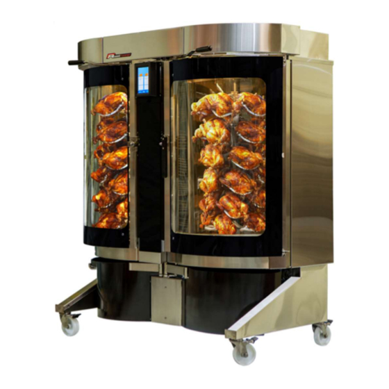
Twin Oven
Installation manual
Your will need the correct PPE and White card to enter building sites.
• Safety glasses must be worn
• Sturdy footwear must be worn
• Gloves must be worn
• Hair must be contained
• No Rings and Jewelry
DO NOT
use this machine unless you have been instructed in its safe
use and operation and have been given permission
NOTE; This manual is prepared for the use of trained Service Technicians.
This manual is intended as a guide. You will need to have the necessary tools/ instruments required.
Reproduction of this Manual, without the express written consent of Technobake Pty Ltd is prohibited.
ACN136 118 253, 11/18 Hinkler Court Brendale QLD 4500Australia
Phone/Fax 61 07 3205 9066
Unit 11 / 18 Hinkler Court, Brendale Qld 4500 Ph 061 7 3205 9066
Single oven
Support Ph 0402 021 190
General Technical Information
Always
all bolts and screws.
Warning:
must comply with local
Water requirements:
ONLY
Warning:
must comply with local sanitary, safety
and plumbing codes.
use never seize/copper slip on
All electrical connections
codes.
COLD WATER
all plumbing connections
Advertisement

Subscribe to Our Youtube Channel
Related Manuals for Technobake Roastrunner

Summary of Contents for Technobake Roastrunner
- Page 1 This manual is intended as a guide. You will need to have the necessary tools/ instruments required. Reproduction of this Manual, without the express written consent of Technobake Pty Ltd is prohibited. ACN136 118 253, 11/18 Hinkler Court Brendale QLD 4500Australia...
-
Page 2: Tools Required For Installation
Introduction to Roastrunner • Twin chamber, sharing electronics, plumbing and fat separator. Operates like two separate ovens. If one chamber has a fault the other chamber will still bake. • ON/OFF switch in the middle, at the bottom of touch screen. Screen is split screen controlling either side of the oven. -
Page 3: Unpacking The Unit
Note: take photos of any damage and send them with a report on the condition of the oven to Service@technobake.com.au. • Remove all packing, cable ties and packing materials, including Fan Packer inside chamber. NOTE: If the gantry does not move freely there could be cable tie holding it in place (one on the inside of the charmer up top and one outside by the catch tray). -
Page 4: Installing The Unit
• Roastrunner oven is to be connected to a AC3 Phase + Earth power supply. Oven supplied with 2M lead and a 5 pin plug. Double oven 50A IP56 - Single 32A. Where more than one outlet is available for the oven, always check rotation is unchanged should socket be changed. - Page 5 • Fit Foot Jack locate lock pin and level oven. Make sure water is level in each chamber with 10mm of wa- ter in the oven floor. Note: the water level is very important as it effect the oven fat separation and drainage.
- Page 6 Connection wires Double and Single To install a combination oven, follow the below format. Two cables -1) 8 core cable (of that only 5 cables are used) 2) Solenoid cable One end of all the needed core cables will be pre-connected to the single oven with labels on them ...
- Page 7 Plumping connections Overflow stops here – Connect to waste – Tundish Maintain a 300mm gap between the two ovens and follow the plumbing above Add the black heat shrink tube over the extension pipe, use any source of heat and make the tube shrink to make the installation look neat and tidy.
- Page 8 Fitting the separator valve and plumbing Connect the 3 way valve and its plumbing to the fat separator by pre as- sembling the valve and its plumping as shown in photo. Push the plastic elbow on as far a it will Then fit the Tri Clover fit- ting and its gasket (right).
- Page 9 Fit the Entry pipe to the separator and slide on as far as it will go. Fit the feed pipe from the floor valve to the separator as shown below. Note the feedpipe from the single chamber oven is fitted enters from the left as shown - if not single oven fitted replace the T with a plastic elbow.
- Page 10 Fat separator operation Method of operation The 3 way valve can be driven by its motor to 3 positions. These are Separator Dump, Drain, and Closed. ‘Separator dump’ will permit the water In the separator tank to remain approximately 2/3 full. This is its normal working position for collecting water throughout the day.
- Page 11 Levelling the Separator Fixing bolts Fat separator level adjustment bolt Tri Clover fittings with Gasket The two mounting bolts on the oven leg, affix the separator tank to the leg, ensuring that the bolts can be loosened to make the setup of water level adjustment possible. Check that oven is in its intended working position on the floor, level oven, lock leg jacks in place.
- Page 12 Configuration How to check and change configuration if needed. Current settings are factory settings and should need no adjustments. Below is how to access if needed. Press Settings press “Configuration” Enter passcode “4500” Press enter Password en- tered correctly you will see this screen Unit 11 / 18 Hinkler Court, Brendale Qld 4500 Ph 061 7 3205 9066...
- Page 13 Diagnostic How to use diagnostic screen. Warning; Fan motors may start without warning when oven is in diagnostic mode. Isolate power to oven before accessing working parts. • Press ‘settings’ Password “2906” From here you can manually run functions of the oven, it will also help quickly diagnose faults. Example; You can test a proximity switch by watching the voltage while using the function if it stays at 0-3.7v its not reading.
- Page 14 If there is anything to report at time of install it must be reported so it can be rectified immediately and If parts are required, we can get them away in a timely manner. Please take Photograph of your installation - front and back and send to service@technobake.com.au (we attach to our data base for that oven) Thank you.
- Page 15 Unit 11 / 18 Hinkler Court, Brendale Qld 4500 Ph 061 7 3205 9066...
- Page 16 Unit 11 / 18 Hinkler Court, Brendale Qld 4500 Ph 061 7 3205 9066...
- Page 17 Unit 11 / 18 Hinkler Court, Brendale Qld 4500 Ph 061 7 3205 9066...
Need help?
Do you have a question about the Roastrunner and is the answer not in the manual?
Questions and answers