Table of Contents
Advertisement
Quick Links
Advertisement
Table of Contents

Subscribe to Our Youtube Channel
Related Manuals for Labomed MAGNA

Summary of Contents for Labomed MAGNA
- Page 1 MAGNA User Manual Operating Microscope Dentistry Part No.: 6129000-795 To ensure proper use of this instrument as well as to avoid injury while operating instrument, Understanding this manual completely before use is highly recommended. Issue 1.7 Printed on May,2020...
- Page 2 The information contained in this document was accurate at the time of publication. Specifications are subject to change without prior notice. LABOMED reserve the right to make changes to the product described in this user manual without notice and without incorporating those changes in any products already sold.
-
Page 3: Table Of Contents
MAGNA LIST OF CONTENTS Introduction, Intended Use and Contraindications Product Description, Floor Stand Product Description, Ceiling Mount Installation References (Ceiling Mount) 4 - 9 Ceiling Mount Installation Drop Ceiling Applications 10 - 11 Leveling The Ceiling Mount System Installing Ceiling Mount On Concrete Ceilings... - Page 4 7. When the microscope is not in use, the suspension arm can be folded over the main body for compact storage. INTENDED USE The Magna microscope is an AC powered device intended for use during diagnosis and surgery to provide a magnified view of the region of interest.
-
Page 5: Product Description, Floor Stand
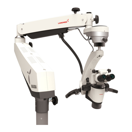
MAGNA 2. PRODUCT DESCRIPTION (FLOOR STAND) Figure-1 1. Caster wheel with Brakes 16. Suspension Arm Hydraulic Movement Lock 2. Cross Base Top 17. Suspension Arm 3. Cross Base Bottom 18. Suspension Arm Spring Tension Adjustment 4. Column 19. Suspension Arm Movement Locking Knob 5. -
Page 6: Product Description, Ceiling Mount
MAGNA 3. PRODUCT DESCRIPTION (CEILING MOUNT) Figure-2 13. Common Main Objective with Fine Focusing 1. Column 14. Left Hand Release (Electromagnetic Clutch) 2. Cover Mount (to be used in false ceiling only) 15. Master Plate 3. Swivel Arm 4. Suspension Arm 5. - Page 7 MAGNA 4. INSTALLATION REFERENCES (CEILING MOUNT) CEILING MOUNT SYSTEM FOR 12 FEET CEILING HEIGHT 1000 170mm Figure-3 Issue 1.7 6129000-795 Magna Printed on May,2020...
-
Page 8: Installation References (Ceiling Mount)
MAGNA INSTALLATION REFERENCES (CEILING MOUNT) CEILING MOUNT SYSTEM FOR 11 FEET CEILING HEIGHT 1000 170mm Figure-4 6129000-795 Issue 1.7 Magna Printed on May,2020... - Page 9 MAGNA INSTALLATION REFERENCES (CEILING MOUNT) CEILING MOUNT SYSTEM FOR 10 FEET CEILING HEIGHT 1000 170mm Figure-5 Issue 1.7 6129000-795 Magna Printed on May,2020...
- Page 10 MAGNA INSTALLATION REFERENCES (CEILING MOUNT) Marking References 175mm 175mm 175mm 175mm 400mm MASTER PLATE Figure-6 Master Plate Spacer Ceiling Mount Column Ø168MM Figure-7 6129000-795 Magna Issue 1.7 Printed on May,2020...
- Page 11 MAGNA INSTALLATION REFERENCES (CEILING MOUNT) Operator Position. Patient is right below the microscope optical head. 1199mm Figure-8 6129000-795 Magna Issue 1.7 Printed on May,2020...
- Page 12 MAGNA INSTALLATION REFERENCES (CEILING MOUNT) 1198mm Operator Position. Patient is right below the microscope optical head. Figure-9 6129000-795 Magna Issue 1.7 Printed on May,2020...
-
Page 13: Ceiling Mount Installation
10. Use a level to ensure the column assembly is Levelled vertically. Refer Section “Leveling the ceiling Mount system” to correct any leveling concerns. 11. All the jobs from Part 1 to 10 here are the responsibility of the customer to provide. Labomed represen tative will complete rest of the microscope Installation after this. - Page 14 MAGNA Wooden membrane Joist Master Plate Shim Column Level Wooden membrane Joist Master Plate Shim Column Heavy Duty vibration free Ceiling Mount Figure-10 Level Normal Ceiling Mount Figure-11 6129000-795 Magna Issue 1.7 Printed on May,2020...
-
Page 15: Leveling The Ceiling Mount System
3. Tighten all screws securely. NOTICE:Shims and Shim materials are to be provided by the customer and are not furnished by Labomed. There are numerous shims and shim materials commercially available and no specific type or brand name is required. -
Page 16: Installing Ceiling Mount On Concrete Ceilings
8. Use a level to ensure the column assembly is Leveled vertically. Refer Section “Leveling the ceiling Mount system” to correct any leveling concerns. 9. All the jobs from Part 1 to 8 here are the responsibility of the customer to provide. Labomed representa- tive will complete rest of the microscope Installation after this. - Page 17 MAGNA INSTALLATION REFERENCES (CONCRETE CEILING MOUNT) RAVAL PLUG M10x75mm SS-854 (8-NOS.) TO BE FIXED IN CONCRETE CEILING BOLT M1Ox75mm SS-854 (8-NOS.) FIXED IN RAVAL PLUG SPRING LOCK WASHER 12MM SS-995 (6-NOS.) BOLT M12x50mm SS-994 (6-NOS.) SS-666 M4x10 PH. PAN HEAD SCREW (10-NOS.)
-
Page 18: Product Description, Wall Mount
MAGNA 6. PRODUCT DESCRIPTION (WALL MOUNT) Figure-18 1. Wall Mount Bracket 2. Mount Shaft 3. Swivel Arm 4. Suspension Arm 5. Suspension Arm Hydraulic Movement Lock Knob 6. Auto Balancing Arm Lock Knob 7. ABA (Auto Balancing Arm) Magnetic Clutch 8. - Page 19 MAGNA INSTALLATION REFERENCES (WALL MOUNT) Operator Position. Patient is right below the microscope optical head. Figure-19 6129000-795 Magna Issue 1.7 Printed on May,2020...
- Page 20 MAGNA INSTALLATION REFERENCES (WALL MOUNT) Rotation of Horizontal Arm about the Column on the Wall Mount is limited with the wall acting as a stop. Rotation of Suspension Arm about the Horizontal Arm on both the Ceiling Mount and the floor stand is 360°.
- Page 21 MAGNA INSTALLATION REFERENCES (WALL MOUNT) Magna Wall Mount with short Arm 750mm 6-COUNTER HOLE Ø16mm x 2.0mm DEEP THRU HOLE Ø11.0mm 500mm 600mm 150mm 346mm 406mm Figure-21 Magna Wall Mount with long Arm 1150mm 6-COUNTER HOLE Ø16mm x 2.0mm DEEP THRU HOLE Ø11.0mm...
- Page 22 MAGNA INSTALLATION REFERENCES (WALL MOUNT) Wall mount: MARKING REFERENCE Anchoring the Wall mount Reference A Paper Template for marking B Wall Mount Assembly C Distance from Floor- Refer suitable height as per ordered configuration from figure-21 or 22 6-COUNTER HOLE Ø16mm x 2.0mm DEEP...
-
Page 23: Wall Mount Installation
Refer to Figure 21 and 22. Measure the distance between the centers of the studs. The Labomed Wall Mount Model is designed to mount directly on a wall with wood studs spaced 406mm (16”) centers or on solid brick/concrete wall minimum 229mm (9”) thick wall. - Page 24 MAGNA 7A. WALL MOUNT INSTALLATION FOR WOODEN WALL 6-NOS HEX HEAD WOODEN SCREW 10x100 6NOS-WASHER CAP RAWAL PLUG M10 PART NO SS-855(6-NOS) Figure-25 6129000-795 Magna Issue 1.7 Printed on May,2020...
- Page 25 MAGNA 7B. WALL MOUNT INSTALLATION FOR SOLID BRICK WALL RAVAL PLUG M10x75mm SS-854 (6-NOS.) TO BE FIXED IN WALL BOLT M1Ox75mm SS-854 (6-NOS.) FIXED IN RAVAL PLUG CAP RAVAL PLUG M10 SS-855 (6-NOS.) Figure-26 6129000-795 Magna Issue 1.7 Printed on May,2020...
-
Page 26: Wall Mount Installation Procedure
MAGNA 8. WALL MOUNT INSTALLATION PROCEDURE 8A.WALL MOUNT INSTALLATION ON STANDARD SIXTEEN INCH(16"406 MM) WOODEN WALL STUD SPACING For securing the Wall Mount System to construction using wooden wall studs spaced on 16 (406 mm) Inch centers, it is recommended that 3/8" x 4" hex head lag screws are used. - Page 27 MAGNA 8A.1. LEVELING THE WALL MOUNT PLATE ASSEMBLY It is important to ensure that wall mount (6137100-806) is level both horizontally and vertically, after installation. Leveling of the wall mount assembly is necessary to prevent the microscope system from drifting from side to side when it is being used at full extension.
- Page 28 Ensuring the wall mount (top edge and front face) is level. NOTICE: Shims and shim materials are to be provided by the customer and are not furnished by Labomed. There are numerous shims materials commercially available and no specific type or brand name is implied.
- Page 29 MAGNA Level Wall Mount Assembly Shim Figure-30 6129000-795 Magna Issue 1.7 Printed on May,2020...
- Page 30 MAGNA 8B.1. LEVELING THE WALL MOUNT ON MASONRY WALL 1. Slightly tighten the bolts on the top side- leaving the bottom bolts slightly loosened. 2. Place a level across the top of the back plate to check the horizontal leveling. See figure-13.
-
Page 31: Construction Requirements (Ceiling/Wall Mount)
MAGNA 9. CONSTRUCTION REQUIREMENTS (CEILING/WALL Mount) 1. The Magna ceiling mount/wall mount must be installed as per detailed in this manual. 2. The construction specialist must confirm in writing that the applicable regional and local codes & regulation have been complied with and that the points listed below have been observed. - Page 32 ANY REPAIR OR SERVICE TO THIS INSTRUMENT MUST BE PERFORMED BY EXPERIENCED PERSONAL OR DEALERS WHO ARE TRAINED BY LABOMED OR SERIOUS INJURY TO THE OPERATOR OR PATIENT MAY OCCUR. WARNING: MODIFICATIONS TO THIS INSTRUMENT ARE NOT ALLOWED. ANY MODIFICATION TO THIS UNIT BE AUTHORIZED BY LABOMED OR SERIOUS INJURY TO THE OPERATOR OR PATIENT MAY OCCUR.
-
Page 33: Warning And Cautions
MAGNA WARNINGS AND CAUTIONS A CAUTION is an instruction that draws attention to the risk of damage to the product. CAUTION: THE INTERNAL CIRCUITRY OF THE INSTRUMENT CONTAIN ELECTROSTATIC SENSITIVE DEVICES (ESD) THAT MAY BE SENSITIVE TO STATIC CHARGES PRODUCED BY THE HUMAN BODY. DO NOT REMOVE THE COVERS WITHOUT TAKING PROPER ESD PRECAUTIONS. -
Page 34: Explanation Of Symbols
MAGNA 11. EXPLANATION OF SYMBOLS Warning: Observe all warning labels and notes! If any label in missing on your instrument or has become illegible, please contact the manufacturer to obtain new labels. Caution label: Observe all caution notes to avoid any unwanted situation with the instrument. -
Page 35: Standards And Directives
MAGNA 12. STANDARDS AND DIRECTIVES The instrument described in this user manual has been designed in compliance with the following standards: • ISO 8600-3 First edition 1997-07-01 AMENDMENT 1 Optics and Optical instruments-Medical endoscopes and endoscopic accessories Part 3: Determination of field of view and direction of view of endoscopes with optics. -
Page 36: Unpacking
MAGNA 13. UNPACKING The appliance is delivered in sub-assembled modular groups along with one Installation Kit and one user manual. Please check for the following when unpacking the device: 1. Mobile Cross base in two parts with brakes on caster wheels or Ceiling Mount or Wall Mount as ordered. -
Page 37: Installation Of Cross Base (Mobile Stand)
MAGNA 14. INSTALLATION OF CROSS BASE (MOBILE STAND) 1. Open the box containing Cross Base Bottom as shown in Fig. 1. Fig. 1 2. Take out the Cross bottom base and put it on floor as shown in Fig. 2. - Page 38 MAGNA 14.1 INSTALLATION OF MICROSCOPE (MOBILE STAND) 1. Open the microscope box. Take out (column) from the box. Mount the column onto a shaft in shaft in base by aligning the Corresponding holes in Column (A) and shaft (B). Secure it with (3) M6x16mm Allen Screws (C) using 4mm Allen Key as shown in fig.-7.
-
Page 39: Installation Of Microscope (Mobile Stand)
MAGNA INSTALLATION OF MICROSCOPE (MOBILE STAND) 4. Install the standard accessories onto the carrier assembly as mentioned below: a. Loosen the M4 grub screw (3) by 2mm allen key and Fix Double iris diaphragm (J) on magnichanger by re-tightening the m4 grub screw. -
Page 40: Electrical Connections
MAGNA 14.2 ELECTRICAL CONNECTIONS Connect the power cable to the AC inlet socket (1) located at the back of the swivel arm as shown in Fig. 11. Switch on the power using the ON/OFF switch (2). Note: The power supply is designed with universal input 100V-240V AC, 50/60Hz. - Page 41 MAGNA ELECTRICAL CONNECTIONS 3. AUTO BALANCING ARM CONNECTIONS a. Connect the 7 pin connector (D) at the 7 Pin female inlet (E) located in Suspension Arm for power in Auto Balancing Arm (ABA) as shown in Fig. 14. b. Take the power wire having 2 pin connectors on both sides...
-
Page 42: Wiring Coding Diagram
MAGNA 14.3 WIRING CODING DIAGRAM 6129000-795 Magna Issue 1.7 Printed on May,2020... -
Page 43: Control Elements
MAGNA 14.4 CONTROL ELEMENTS ON / OFF SWITCH The ON/OFF switch (A) is located at the back of the swivel arm. In the ON position, a green LED (B) glows, and the cooling fan starts running as shown in Fig. 15. - Page 44 MAGNA CONTROL ELEMENTS LOCKING KNOBS a. Swivel Arm Locking Knob This knob shown as (G) locks the movement of the Swivel arm at the desired position by turning it Clockwise as sho- wn in Fig. 17. b. Suspension Arm Locking Knob...
- Page 45 MAGNA 15. USING THE MICROSCOPE WARNING: INSTRUMENT IS UNSAFE FOR MRI ENVIRONMENTS. CAUTION: Upon Installation, ABA System may feel stuck due to longtime Inoperative in transit or storage. This temporary mild locking may happen due to material Property of ABA braking Material.
-
Page 46: Using The Microscope
(A.1) on Right handle to Centre the area of interest in the field of view as shown in Fig. 19. Main Microscope Configuration: Magna comes with standard accessories mentioned below: a. NuVar variable objective, focal length 300-400mm (standard). b. 0˚- 210˚ tiltable ergo binocular tube. - Page 47 MAGNA 16. USE OF ACCESSORIES Model: Magna MASTER PLATE 6129004-051 RETICULE RETICULE 10X EYE PIECE 12.5X EYE PIECE MONITOR ARM CEILING MOUNT 6129010 6129012 6129001-876 6129001-841 WALL MOUNT CEILING MOUNT 6129002-805 6129001-801 MONITOR ARM 6129004-810 TILTABLE ERGO HEAD (0-210°) 6122015 ARM ASSEMBLY WALL &...
-
Page 48: Use Of Accessories
MAGNA USE OF ACCESSORIES 1. Rotoplate: Rotoplate eliminates neck craning, making it comfortable to view hard to see region of mouth from 9 and 3’O clock seated position. 2. DBSi (Double Beam Splitter Inclined): A beam splitter divides the light into two beams, it can be 50:50 or 80:20. -
Page 49: Thermal Cut-Off
MAGNA 17. THERMAL CUT-OFF The instrument is designed with safety provisions. Fans in the electrical box provide free- and forced- air circulation to cool the electronic components. The instruments also includes a built-in-safety mechanism called “auto thermal cut-off”. This mechanism is activated through Thermistors when the LED temperature rises above 80°C. -
Page 50: Moving & Storage The Instrument
MAGNA 19. MOVING & STORAGE THE INSTRUMENT Fold the system as shown before moving & during storage Fig. 25 MOVING THE STAND 1. Turn off the unit at the power switch. 2. Disconnect the power cable. 3. Remove the video cable from the video modules (e.g., video monitor, USB monitor) and the camera control unit. -
Page 51: Care And Maintenance
MAGNA 20. CARE AND MAINTENANCE This instrument is a high grade technological product and does not require any special periodical Maintenance if handled carefully. Still to ensure optimum performance and safe working order of the instrument, it’s safe functioning must be checked periodically as per table below. We recommend having this check performance by our service representative as part of regular maintenance work. - Page 52 Do not use ethanol and spirit. 10. Do not clean products and optical components in a cleaning/disinfecting devices or ultra sound bath. 11. LABOMED Max Lite coating are fungal resistant. If you clean as described above, the coatings will not be damaged.
-
Page 53: Cleaning And Disinfection
2. While cleaning, muslin cloth should not be dripped wet to prevent seepage and rusting to running/bare parts. 3. Alcohol is flammable,its use as a surface disinfectant should be in well-ventilated spaces only. MAGNA 22. AUTOCLAVING The rubber caps, sleeves and grips supplied by labomed are recommend for the following program for autoclaving: • Temperature: 134˚C •... - Page 54 MAGNA 23. SCHEDULE OF AUTOCLAVE CAPS Autoclave Caps Lock Knob Covers for Arm Movement: 1. Knobcover-Partno.6129000-237 2. Knobcover-Partno.6129000-237 3. Knobcover-Partno.6129000-237 4. Knobcover-Partno.6129000-237 Knob for Illumination Control: 5. Silicon Cover - P/N.6122015-210 Knob for IPD (inter-pupillary distance): 6. Silicon Cover - P/N.6122015-210 Knob for Clutch Handle (right side): 7.
-
Page 55: Ambient Requirement
MAGNA 24. AMBIENT REQUIREMENT +10˚C..+40˚C For Operation Temperature Rel. Humidity 30%..90% (without condensation) Air Pressure 700hPa..1,060hPa -10˚C..+40˚C Temperature For Transportation and Storage Rel. Humidity 30%..90% (without condensation) Air Pressure 700hPa..1,060hPa The unit meets the essential requirements stipulated in Annex I of the 93/42/EEC directive governing medical devices. -
Page 56: Technical Specification
MAGNA 26. TECHNICAL SPECIFICATIONS Robust, vibration-free stand on a cross base with four 1. Stand lockable caster wheels 0-210° tiltable head configured with Rotoplate, DBSi 2. Binocular Tubes (Double Beam Splitter Inclined), Double Iris Diaphragm and DSLR Adapter 50 - 75mm 3. - Page 57 MAGNA 27. TROUBLESHOOTING TABLE Problem Possible Cause Remedy Plug in power cable No illumination Power cable not plugged in Press the power switch to ON Power switch in OFF position position Defective instrument fuse Change the fuse Change the power cable...
-
Page 58: Troubleshooting Table
MAGNA TROUBLESHOOTING TABLE Problem Possible Cause Remedy The brakes on the wheels are not Engage the brakes Stand is unstable in use Magnichanger is not indexed Rotate the Magnichanger to click No image is visible in the properly a stop... - Page 59 All Equipment and Systems Guidance and Manufacturer’s Declaration - Electromagnetic Emissions Magna is intended for use in the electromagnetic environment specified below. The customer or user of the Magna should ensure that it is used in such an environment. Emissions Test...
-
Page 60: Guidance Tables
All Equipment and Systems Guidance and Manufacturer’s Declaration – Electromagnetic Emissions Magna is intended for use in the electromagnetic environment specified below. The customer or user of the Magna should ensure that it is used in such an environment. Compliance Level... - Page 61 Equipment and Systems that are NOT Life-Supporting Guidance and manufacturer’s Declaration – Electromagnetic Immunity Magna is intended for use in the electromagnetic environment specified below. The customer or user of the Magna should ensure that it is used in such an environment.
- Page 62 The Magna is intended for use in electromagnetic environments in which radiated RF disturbances are controlled. The customer or user of the Magna can help prevent electromagnetic interference by maintaining a minimum distance between portable and mobile RF communications equipment (transmitters) and the Magna as recommended below, according to the maximum output power of the Communication equipment.
-
Page 63: Dimensions And Weight
MAGNA 29. DIMENSIONS AND WEIGHT Ceiling Mount Wall Mount Floor Stand Configurations Weight Magna with Wall Mount a. Wall Bracket 12Kg b. Shaft 07Kg c. Magna Arm Long/Short 18Kg/14.5Kg d. Magna Carrier 11Kg Magna with Ceiling Mount a. Ceiling Mount 30Kg b. -
Page 64: Glossary
MAGNA 30. GLOSSARY Compensation of short-or-far-sightedness. This can be done for each Ametropia Compensation Eye using the two individual eyepieces (range: +5 to -5 diopters). Distance from the common main objective (COM) to the object or area Working Distance Of interest. -
Page 65: Warranty
LABOMED factory or authorized LABOMED Dealer. All claims under this warranty must be in writing and directed to the LABOMED factory or its Authorized dealer for this device making the original sale and must be accompanied by a copy of the purchaser’s invoice. -
Page 66: Magna Issue
MAGNA WARRANTY (continued) CLAIMS FOR DAMAGES IN TRANSIT Our shipping responsibility ceases with the safe delivery in good condition to the transportation company. Claims for loss or damage in transit should be made promptly and directly to the Transportation company. - Page 67 920 Auburn Court Fremont, CA 94538 U.S.A. Phone: 510-445-1257 Fax: 510-991-9862 Email: sales@laboamerica.com www.laboamerica.com EU REP. Labomed Europe Essebaan 50 NL-2908 LK Capelle a/d IJssel The Netherlands Tel: +31 (0)10 4584222 Fax: +31 (0)10 4508251 E-mail: info@labomedeurope.com A16372 ISO 13485...
Need help?
Do you have a question about the MAGNA and is the answer not in the manual?
Questions and answers