Table of Contents
Advertisement
Newton+ – Operational Manual
U
M
SER'S
ANUAL
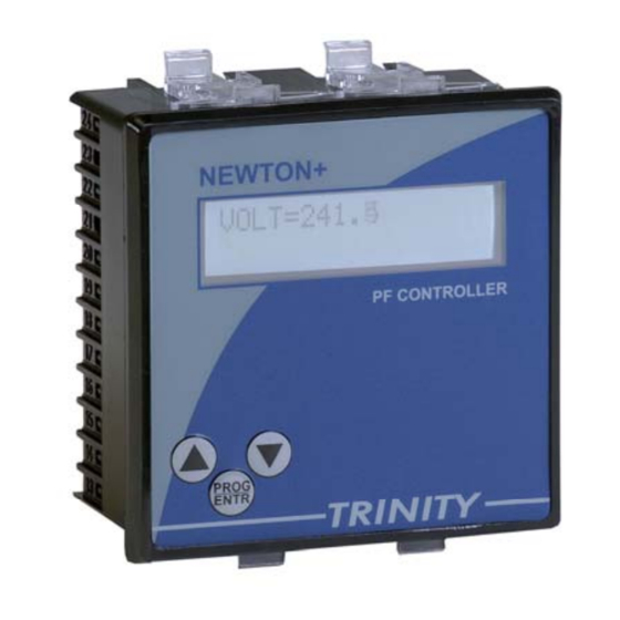
Newton+
AUTOMATIC POWER FACTOR CORRECTION RELAY
This document contains the latest technical information about Automatic Power
Factor Correction Relay, Newton+ which is a micro-controller based KVAR controller.
The product, Newton+ is sophisticated electronic equipment and, the user is advised
to read this User's Manual carefully before attempting to install or operate the
equipment.
Published on: (mention the date of publishing)
Document Version: 1.0
TRINITY
[1]
Advertisement
Table of Contents

Related Manuals for Trinity Newton+

Summary of Contents for Trinity Newton+
- Page 1 Factor Correction Relay, Newton+ which is a micro-controller based KVAR controller. The product, Newton+ is sophisticated electronic equipment and, the user is advised to read this User’s Manual carefully before attempting to install or operate the equipment. Published on: (mention the date of publishing) Document Version: 1.0 TRINITY...
- Page 2 In the event, the remedies above fail, Trinity’s entire liability shall be limited to a refund of the price paid for the Trinity product covered by this limited warranty. Except as provided in this written warranty, neither Trinity Energy Systems Pvt.
-
Page 3: Table Of Contents
11. Performing Autosense of Capacitor Bank ........... 16 Run Mode ....................... 18 1. Screen Displays ....................18 Control Outputs ......................19 (A) Trouble Shooting ..................... 19 (B) Trouble Shooting Guide ................... 22 TRINITY... -
Page 4: Introduction
6. Capacitor CT rating must be calculated for autosense as, CT Primary Total KVAR X 1.6 7. Check all these points carefully in the system. If found ok, installation and commissioning of the relay is easy. TRINITY... -
Page 5: The Main Features Available In This System
Programmable Time Delay for step switching System KVAR value Selectable Capacitor Bank Stages and Autosense of its bank sizes Selectable for Run Mode display Scroll and Unscroll Measurement of System Active Power (KW). NEWTON+ 16X2 LC DISPLAY TRINITY... -
Page 6: Technical Specifications
Range of Reading : 0.05 to 1.00 Lag/Lead Bezel 96X96 mm Depth of installation 55 mm Operating temp 10°C to 50°C Weight 0.3 kg (aprox.) Min. Operating Current 1% of CT Primary in VAR mode, 6% in PF mode. TRINITY... -
Page 7: Installation And Commissioning
M and S2 from CT goes to L on the unit. Make sure that the three phases coming to the unit come through control fuses 1.0 Amp rating. This will protect the electronics inside from damage due to severe over voltages or phase faults in the system. TRINITY... - Page 8 5. Switch on the three phases supply, the unit will then prompt a power receiving information such as - - - TRINITY- - - -for about 2 to 3 seconds. 6. First of all, user should program the following parameters of the unit: such as Control Mode of operation, Main CT-Ratio, Scroll Seconds, desire PF, Time Delay, On Delay, Off Delay, Bank Stages, Minimum Bank and Autosense.
-
Page 9: Connection Scheme
NEWTON+ – Operational Manual Connection Scheme TRINITY... -
Page 10: Operational Details
After supplying power (80 VAC - 240 VAC) to the three phases, the unit displays immediately power receiving information, - - - TRINITY- - - - on LCD screen and by default, the display comes into Run Mode such as shown below. -
Page 11: Programming Mode
Set the desired Control mode by pressing keys and then, press key to confirm the parameter setting. 3. The unit will automatically reset and return into Run Mode. In case, your setting is not completed, proceed the above instruction to specify for other parameters. TRINITY [11]... -
Page 12: Setting The Main Ct Ratio
3. In case, your setting is completed, press key for about 4 to 5 seconds to return into Run Mode. Or press keys to specify for other parameters such as above instructions. TRINITY [12]... -
Page 13: Setting Scroll Display In Run Mode
Set PF such as shown below. SET_PF=1.0 2. Press key. Immediately, P starts blinking which shows that the parameter can now be changed. Set the desired PF by pressing keys and then, press key to confirm the parameter setting. TRINITY [13]... -
Page 14: Setting The Time Delay In Between Stages
On Delay such as shown below. ON DELAY=10 2. Press key. Immediately, P starts blinking which shows that the parameter can now be changed. Set the desired On Delay by pressing keys and then, press key to confirm the parameter setting. TRINITY [14]... -
Page 15: Setting Off Delay With Leading Pf
To select the Stages, proceed the following instructions: 1. In Run Mode, press key for about 4 to 5 seconds and then the unit will enter into Programming Mode. Press key to receive the Bank Stage such as shown below. STAGE=8 TRINITY [15]... -
Page 16: Selecting For A Sense In Percentage Of Minimum Bank
To set the Autosense of capacitor, proceed the following instructions: 1. In Run Mode, press key for about 4 to 5 seconds and then the unit will enter into Programming Mode. Press key to receive the Auto Sense such as shown below. TRINITY [16]... - Page 17 3. In case, your setting is completed, press key for about 4 to 5 seconds to return into Run Mode. Or press keys to specify for other parameters such as above instructions. TRINITY [17]...
-
Page 18: Run Mode
LC at right side of the parameter. The third display shows system PF. PF= 1.000 KVAR=32.42 The fourth display shows the system KVAR. The fifth display shows the system Active Power KW=50.4 (KW). TRINITY [18]... -
Page 19: Control Outputs
Faults related to the actual system design: The most common faults are: External Manual Control not implemented properly Here many designers provide a ‘Starter-relay’ configuration for the manual control, and just bring the connection from the relay contact to the contactor. TRINITY [19]... - Page 20 However, the transformer losses will cause the monthly average PF to show up as very poor. The remedy is to connect a small bank directly (independent of the automatic control scheme) for compensating transformer losses. TRINITY [20]...
- Page 21 Blown fuses, shorted CT, shorted voltage connections, switches that do not make contact, open connections etc. Check everything - before, during and after commissioning and you will be rewarded with a finely tuned system which will give you years of trouble-free service. TRINITY [21]...
-
Page 22: (B) Trouble Shooting Guide
The contactors are latching up through their holding contacts. Extensive rewiring is required to remedy this fault. This is also possible if 440 VAC coils have been used. 6. Relay is on but PF meter indicates 1.0 always. The current through the Relay is inadequate. TRINITY [22]... - Page 23 Specifications/Literature/O & M Manual. Traceability: tested against latest "MTE" Standard Model PRS400.3 having basic accuracy of 0.02% traceable upto International Standards derived using appropriate ratio techniques. Result of Test : ………………………………………………………………… Remarks : ………………………………………………………………… Test engineer : ………………………………………………………………… Date : ………………………………………………………………… TRINITY [23]...
Need help?
Do you have a question about the Newton+ and is the answer not in the manual?
Questions and answers