Table of Contents
Advertisement
Advertisement
Table of Contents

Subscribe to Our Youtube Channel
Related Manuals for Murska 700HD

Summary of Contents for Murska 700HD
- Page 1 Murska 700-1000HD Manual Frame Cassette Bagger Version 1.0 13.6.2014...
-
Page 2: Table Of Contents
TABLE OF CONTENTS DECLARATION OF CONFORMITY ....................3 WARRANTY ............................3 DESCRIPTION ............................4 TECHNICAL INFORMATION......................6 Safety instructions ........................... 7 START-UP ............................10 Start-up after delivery ........................10 Connecting to the tractor ....................... 10 PTO shaft ............................11 Installing the elevator ........................12 INSTRUCTIONS FOR USE ......................... -
Page 3: Declaration Of Conformity
Name and address of the person authorised to compile the technical file: Name: Aimo Korte Address: P.O. Box 161, FI-84101 YLIVIESKA, Finland hereby declares that Murska ________________________ -crimper Serial number: ………………………….. Bagger: ………………. is in conformity with the relevant provisions of the Machine Directive 2006/42/EY Place, Date: Ylivieska 20.12.2013... -
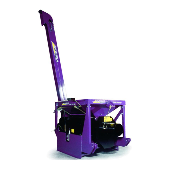
Page 4: Description
DESCRIPTION Purpose of use: Storing of crimped harvest-moist feed grains, crimping and grinding of dry and acified grain, peas, beans etc. for feed. Manufactured in Finland (EU) Serial number plate for roller cassette Serial number plate for Serial number plate crimper frame Serial number Model... - Page 5 Reference Numbers: 1 ..Handle for feeding door 12 ..Elevator maintenance door 2 ..Flange nut 13 ..Flow meter 3 ..Roller adjustment bolt 14 ..Elevator top hat 4 ..Elevator guard bolt 15 ..Elevator chain adjuster 5 ..
-
Page 6: Technical Information
TECHNICAL INFORMATION Machine Murska 700HD Murska 1000HD Crimping capacity 7000-10 000 kg/h 10000-15000 kg/h Power demand (750rpm) 20-50 KW 30-65 KW Hopper capacity 380 liters 330 liters Elevator lifting height 3300 mm 3300 mm Length (elevator model) 1450 mm 1800 mm... -
Page 7: Safety Instructions
Safety instructions 1. Always keep the grinder on the 5. Do not stand on the PTO shaft ground or on a steady surface or between the tractor and the during use. All guards must be machine. installed correctly. 2. Do not move the mill during use, 6. - Page 8 V-belts and pulleys – hand Turning cogwheels – arm may or arm may become become entangled. entangled. Never open or remove the Lubrication point. guards when the motor is running. Never reach or climb into the hopper when the motor is running.
- Page 9 …Safety instructions Grain container: moving parts, danger of entanglement Never climb into the grain container when the crimper is running! Check the tightness of fastener bolts regularly. Never put tools, clothes or your hand into the grain container. Connecting to the tractor ...
-
Page 10: Start-Up
8) Make sure that the hopper, feeder, roller cassette, auger or any other part of the device does not contain any foreign objects. Connecting to the tractor Murska 700-1000HD bagger models are designed to be connected to the tractor trailer connector. Murska 700-1000HD elevator models are connected to the three-point hitch of the tractor. -
Page 11: Pto Shaft
* The recommended PTO shaft for 700-1000HD –crimper is: * PTO shaft with slip clutch * Torque: * 700HD: 2000 Nm * 1000HD: 2000 Nm * (e.g. Bondioli size 8, slip clutch) * The PTO shaft safety clutch must be installed on the side of the machine. -
Page 12: Installing The Elevator
Installing the elevator 1. Fix the chain tensioner adjustment bolts to the top of the elevator chute. 2. Push the chain tensioner/sheave into the sliding sleeve and tighten the adjustment bolts. 3. Pull the chain into the elevator. 4. Ensure the correct position of the chain... - Page 13 5. Attach the elevator to the flange on the 6. Attach the head of the elevator. Make sure transporter and lock and tighten the chain that the output direction is right appropriately. Example of elevator head adjustment...
-
Page 14: Instructions For Use
INSTRUCTIONS FOR USE Recommendations 1. Routine checks before use Perform these checks every time the device is used after it has been unused for a while and before any other maintenance is performed. 2. Adjusting rollers Roller adjustments are always checked before starting the machine and after any maintenance work. -
Page 15: Routine Checks Before Use
Routine checks before use 1. Check that all screws and bolts are tight enough. Replace any worn or rusty parts. 2. Place the elevator in an upright position and check elevator chain tightness at the tensioner. Movement in line with the tensioner’s axis is allowed. Adjust the gear at the top of the elevator if necessary. -
Page 16: Basic Roller Adjustments
Basic roller adjustments The rollers must always be adjusted at the beginning and during the harvest season. If the machine is in constant use, check the adjustments daily. Checking the rollers 1. Adjust the roller clearance to the minimum using the adjustment crank (to open, turn counter-clockwise). - Page 17 3. Measure the roller clearance at both ends using a feeler gauge. The minimum clearance is 0.3mm The roller clearance must be same at both ends, i.e. the rollers must be perfectly aligned. Picture. Measuring the roller clearance 4.
- Page 18 Roller adjustment Roller adjustment is always carried out for both roller pairs, one side at a time. The mill is delivered with default adjustments. NOTE! If the rollers touch each other when turning, they may wear out very fast. The warranty will not cover wear that results from incorrect use of rollers.
- Page 19 Wind the roller clearance adjustment crank (1) so that the adjustment shaft arm is at the furthest position. Finger tighten the adjustment screws (3) Tighten the adjustment screws (3) half a turn using a wrench Adjust the roller clearance to 0.3mm at both ends using a feeler gauge Tighten the locking nuts (5) The mill is now appropriately adjusted and you can start crimping.
-
Page 20: Start-Up, Starting Crimping And Use
5. Make sure that all guards are correctly placed and installed. 6. Close the feeder hatches. 7. Fill up the hopper with grain. 8. Apply maximum tension to the roller springs: (700HD ca. 120bar. and 1000HD ca. 140bar.) 9. Engage tractor PTO at 540rpm. -
Page 21: Ending Crimping
Ending crimping 1. Switch off the acid pump and close the feeder hatch. 2. Keep the mill running until all grain has been crimped and the auger / elevator no longer produces crimped grain. 3. Disengage the PTO drive and stop the tractor. Disconnect the PTO shaft. 4. -
Page 22: Brakes
Brakes Bagger Baggers use a hydraulic hand pump for braking during bagging and as the parking brake. The system includes the pump, pressure gauge and a ball valve. Use wheel chocks while the machine is not being used. The pressure screw in the pump must be closed while pumping the pressure. The ball valve locks the brake system pressure. -
Page 23: Maintenance
MAINTENANCE Stop the tractor and disengage the PTO drive before performing any maintenance work. Daily maintenance Check the v-belts The condition of the elevator auger v-belt and tensioner Check the auger chain The condition of the bagger auger chain, chain wheel and lubrication system. Add more lubricant if necessary. -
Page 24: After The Season
After the season 1. Clean the mill thoroughly using a pressure washer. However, do not point the pressure washer directly at bearings or bearing housing. 2. Remove the elevator chain, lubricate it e.g. by dipping it into a container with oil and place it back. -
Page 25: Maintenance Chart
If the painted surface has been damaged, sand any rust away and paint with anti-corrosive primer and top coat. You can order Murska touch-up paint from the factory. = Disconnect the elevator chain and lubricate it by dipping it into an oil container. -
Page 26: Instructions
INSTRUCTIONS Changing the roller cassette 1. Detach the scraper knife spring and knives, if another cassette includes different kinds of knives. 2. Detach the covers and the possible additional container. - Page 27 3. Detach the hopper handles 4. Remove the hopper’s safety grid...
- Page 28 5. Remove the magnet set 6. Detach the regulation handle 7. Support the adjustable roller, loosen the jack and turn it over.
- Page 29 8. Release and remove the hopper bolts and remove the hopper by lifting. 9. Remove the 6 roller cassette bolts (19mm wrench).
- Page 30 10. Lift the roller cassette off of the frame. Note! Cassette frame: 700HD ca. 360 kg, 1000HD ca. Installation of the roller cassette is done in reverse order. The roller cassette must be carefully installed whenever replaced and installed. The machine is now ready for the roller adjustment (see p. 18).
-
Page 31: Screw Torque
Screw torque Size Torque [Nm] Structural performance 10.9 1050 Pulley assembly The cast iron pulleys are fastened to the shaft with a separate taber hub. Assembly 1. Clean protective grease from taper hub and pulley nave. 2. Place taper hub inside the pulley nave and align the holes. 3. - Page 32 Disconnecting 8. Release and remove the screws. 9. Screw one of the screws in the pulling hole (threaded hole in the taper hub). 10. Tighten the screw until the taper hub is removed from the shaft. 11. Remove the pulley and taper hub from the shaft. Hole for the out-pull screw, thread in the taper hub.
-
Page 33: Possible Disruptions
POSSIBLE DISRUPTIONS 1. Low power, dough on the rollers, roller discs heat up roller clearance is too small scraper knives are not functioning properly. Increase the roller clearance and check the scraper knives under the rollers, clean them and ensure that they scrape the roller surface in an even manner. Lower the rotation rate so that the grain passes through the rollers and does not remain on top of the rollers. - Page 34 6. Slip clutch fails: Momentary overload. Ensure that the feeding of grain onto the rollers is even. 7. The crimping result is too coarse: The adjustment crank adjustment is too far. Adjust the rollers closer to each other using the coarse adjustment screw. If this does not improve the result, decrease the feeding volume.
-
Page 35: Using The Bagger 700-1000Hd
USING THE BAGGER 700-1000HD 1. Lower the bagger bottom plate, supported by the chains. Place the bag on the tunnel in between the pipes. Make sure the direction is correct: the folded bag will unfold from the bottom. The correct bag size is Ø2.0–2.2m 2. - Page 36 4. Close the end of the bag carefully by tying it with a piece of string. Tuck the end of the bag under the bottom plate of the tunnel. 5. The tube should be made on an even and compact surface. Start making the tube against a wall, round bale or similar support.
- Page 37 6. Lock the tyres pumping maximum pressure to the hydraulic brakes (150–170 bar). 7. Ensure that the brakes of the tractor are off and the tractor is out of gear. The grain pushed into the tube by the bagger screw will push the tractor and bagger forward. The tractor drive is running the mill and the bagger at 540/min.
- Page 38 10. Now the bagger screw will start pushing crimped and acidified grain into the tube. Note! The bagger screw will grind the crimped grain for a second time so the roller clearance can be kept bigger than normally. 11. When the end of the bag is starting to be full and the bag starts stretching, release the brake valve carefully (to around 70–100 bar) so that the machine will start slowly moving forward.
- Page 39 13. When bagging is finished, close the feeder to rollers first and then continue crimping until the rollers are empty and stop the mill. Release the brake pressure and drive the tractor slowly forward 2–3 metres so that an empty stretch of bag will be unfolded. 14.
-
Page 40: Notes
NOTES... - Page 44 Aimo Kortteen Konepaja Oy P.O. Box 161, (Pohjolantie 2) FI-84101 YLIVIESKA, Finland Tel. +358 8 411 0500 Fax: +358 8 425 422 E-mail: info@murska.fi Website: www.murska.fi...
Need help?
Do you have a question about the 700HD and is the answer not in the manual?
Questions and answers