Table of Contents
Advertisement
Advertisement
Table of Contents

Related Manuals for Pulse fitness 280G-B

Summary of Contents for Pulse fitness 280G-B
- Page 1 280G-B / 280G-F Assembly, Operation & Parts Manual (Reference) EU/US...
- Page 2 Company Addresses Global Corporate Headquarters Regional (Distributor/Dealer) Address(es) Address: Current List of Distributors/Dealers: Pulse Fitness Ltd., Radnor Park, Greenfield Road, Congleton, https://www.thepulsegroup.co.uk/pulse-global Cheshire, CW12 4TW, England, United Kingdom Sales/Marketing: Americas Tel: +44 (0)1260 294600 North America Fax: +44 (0)1260 299282 Email: info@pulsefitness.com...
- Page 3 This manual describes the equipment's setup its installation and instructs how to use it correctly and safely. It is of the utmost importance that any User of the PULSE FITNESS X-Train (Elliptical Cross-Trainer) is fully trained in its operation! Please ensure that the instructions given in General Safety Precautions section are understood by ALL Users.
- Page 4 Overview (Continued) Statement of Purpose: The elliptical cross-trainer is an exercise machine that combines low impact elliptical pedalling, where resistance is independent of speed, with push/pull arm motion to provide an efficient, effective total-body workout FCC Warning - Possible Radio / Television Interference. NOTE: This equipment has been tested and found to comply with the limits for a Class A digital device, pursuant to part 15 of the FCC rules.
-
Page 5: Table Of Contents
3.12 Attaching the Neck Battery Powered - Series 1 & 2 3.13 Attaching the Dashboard Valance Where to Place the 280G-B / 280G-F 3.14 Attaching the Front Dashboard Moulding How to Stabilise the 280G-B / 280G-F 3.15 Attaching the Rotating Endcaps Install a PSU for Series 3 Console 3.16 Fitting Storage Buckets... - Page 6 Table of Contents (Continued) 10.1 Location 10.2 Feet Adjustment 10.3 On/Off Switch Cleaning & Maintenance 11.1 Preventive Maintenance Tips 11.2 Cleaning the Equipment 11.3 Compatible Cleaners 11.4 Preventive Maintenance Schedule 11.5 How to Obtain Product Service 11.6 Recycling the Battery Specifications 12.1 Specifications...
-
Page 7: Overview Of 280G-B / 280G-F
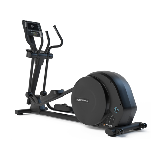
280G-B Overview 280G-B X-Train Console (Series 1, 2 or 3) Storage Bucket Fixed Handles Transport Wheels Book Rest Handpulse Sensor Drinks Bottle iPod / iPhone Dock ® ® Levelling Foot Articulated Pedals Assembly, Operation & Parts Manual G-Range... - Page 8 280G-F Overview (Continued) 280G-F X-Train Console (Series 1, 2 or 3) Storage Bucket Fixed Handles Transport Wheels Book Rest Handpulse Sensor Drinks Bottle iPod / iPhone Dock ® ® Levelling Foot Fixed Pedals Assembly, Operation & Parts Manual G-Range...
-
Page 9: Contents Of 280 G-B / 280 G-F Pack
Contents of the 280G-B Pack The 280G-B X-Train will have to be assembled from the flat pack. The contents of the pack are as follows: Main Body Moving Handlebars iPhone / Pod Dock ® ® Front iPod Moulding ® Top Assembly... - Page 10 (Series 1, 2 or 3) Column Rotating Endcaps Pivot Covers Front Joint Mouldings Console Bolts Column Bolts [Top] Console Column/Neck Bolts Cladding Screws If any parts are missing then please contact PULSE FITNESS' Global Service Team +44(0)1260 294600. Assembly, Operation & Parts Manual G-Range...
-
Page 11: Assembly Of 280G-B / 280G-F
Assembly of 280G-B Figure A 3.1 Securing the Column Securing the Column Rest the Column onto something stable e.g. a box or equivalent, and thread the Cable Loom up through it, whilst making sure that the loom does not get trapped. - Page 12 Assembly of the 280G-F (Continued) Figure A 3.1 Securing the Column Securing the Column Rest the Column onto something stable e.g. a box or equivalent, and thread the Cable Loom up through it, whilst making sure that the loom does not get trapped.
-
Page 13: Connecting The Cables
Assembly of the 280G-B / 280G-F (Continued) Figure B 3.2 Connecting the Cables Connecting the Cables With care, connect the cables into the correct ports to the PCB attached to the front joint. [See Figure NOTE: Make sure that the cables do not get trapped during this process and are not tight. -
Page 14: Attaching The Front Joint Mouldings
Assembly of the 280G-B (Continued) Figure C 3.3 Attaching the Front Joint Mouldings Attaching the Front Joint Mouldings Attach the Front Joint Mouldings to the main frame with the screws, being careful not to damage any cables or PCB in the process. [See Figure C]. - Page 15 Assembly of the 280G-F (Continued) Figure C 3.3 Attaching the Front Joint Mouldings Attaching the Front Joint Mouldings Attach the Front Joint Mouldings to the main frame with the screws, being careful not to damage any cables or PCB in the process. [See Figure C]. NOTE: Make sure that both the cable-loom or PCB do not get damaged or trapped during this process.
-
Page 16: Attaching The Moving Handlebars
Assembly of the 280G-B / 280G-F (Continued) 3.4 Attaching the Moving Handlebars Slide the arms onto the shaft (the arms are handed). [See Figure D]. NOTE: Make sure that the cables from the handpulse do not get trapped during this process. -
Page 17: Securing The Moving Handlebars
Assembly of the 280G-B / 280G-F (Continued) Figure E 3.5 Securing the Moving Handlebars Securing the Moving Handlbars Secure the moving bars into position by inserting the Bolts and Washers into the pivot shaft. [See Figure E].Check that the arms move freely without any excessive play. -
Page 18: Secure Pivot Shaft
Assembly of the 280G-B / 280G-F (Continued) Figure F 3.6 Secure Pivot Shaft Secure Pivot Shaft Secure the pivot shaft into position with the grub screws. [See Figure F]. Tools Required: 5mm Allen Key [M12 Cap Head] Assembly, Operation & Parts Manual... -
Page 19: Attaching The Moving Handlebars To Foot Bars
Assembly of the 280G-B / 280G-F (Continued) 3.7 Attaching the Moving Handlebars to the Foot Figure G Bars Attaching the Moving Handlebars to the Foot Bars Attach the Moving Handlebars to the Footbars by inserting handlebar spacer washers either side of the bearing. -
Page 20: Secure Moving Pivot
Assembly of the 280G-B / 280G-F (Continued) 3.9 Secure Moving Pivot Figure I Secure Moving Pivot Secure with handlebar bolt and washer on the outside. Ensure that the assembly is correct before securing pivot mouldings. [See Figure I]. Tools Required: 6mm Allen Key [M12 Cap Head] 3.10 Attaching the Pivot Mouldings... -
Page 21: Attaching The Ipod Dock/Storage Station Dashboard
Assembly of the 280G-B / 280G-F (Continued) Figure K 3.11 Attaching the iPod Dock/Storage Station ® ® Attaching the iPod Dock/Storage Dashboard Station Dashboard Place the iPod Dock Dashboard onto the top ® bracket assembly, positioning the moulding snug against the fixed handlebars and neck. You may need to tilt the moulding into position. -
Page 22: Attaching The Neck
Assembly of the 280G-B / 280G-F (Continued) 3.12 Attaching the Neck Drop the neck through the hole in the upper assembly bracket and secure with bolts. [See Figure L ]. NOTE: Ensure that a rubber neck gasket has been fitted onto the neck before fastening to the bracket. -
Page 23: Attaching The Dashboard Valance
Assembly of the 280G-B / 280G-F (Continued) Figure M 3.13 Attaching the Dashboard Valance Attaching the Dashboard Valance Attach the Dashboard Valance by pushing it up ® snug against the iPod Dock/Storage Station top moulding and fastening together with 3x screws. -
Page 24: Attaching The Front Dashboard Moulding
Assembly of the 280G-B / 280G-F (Continued) 3.14 Attaching the Front Dashboard Moulding Attach the Front Dashboard Moulding by lining it up against the existing Dashboard and Valance. Then secure into position with 2x screws. [See Figure N]. NOTE: Make sure that all the mouldings line up and do not overlap before tightening the screws. -
Page 25: Attaching The Rotating Endcaps
Assembly of the 280G-B / 280G-F (Continued) Figure O 3.15 Attaching Rotating Endcaps Attaching Rotating Endcaps Attach the Rotating Encdaps by lining each pair up against the rotating handlebar bosses, and securing with 3x screws. [See Figure O]. NOTE: Make sure that a fixed handlebar gasket has been fitted before attaching Endcaps. -
Page 26: Fitting Storage Buckets
Assembly of the 280G-B / 280G-F (Continued) Figure P 3.16 Fitting Storage Buckets Fitting Storage Buckets Insert the Storage Buckets into the Dashboard hoops and press down firmly. [See Figure P]. Assembly, Operation & Parts Manual G-Range... -
Page 27: Installing The Console On 280G-B / 280G-F
Installing Consoles on the 280G-B / 280G-F Figure Q Figure R 4.1 Securing the Console Securing the Console Assembling the Console Place the bottom half of the Console onto the Column and secure with the Console Bolts. [See Figure Q]. -
Page 28: Wiring The Console
Installing Consoles on the 280G-B / 280G-F (Continued) Figure S 4.3 Wiring the Console Wiring the Console Carefully pull the Electrical Connectors up from the Column. Ensure that all the Electrical Connectors attach to the Circuit Board as shown*. [See Figure... -
Page 29: Assembling The Console
Installing Consoles on the 280G-B / 280G-F (Continued) Figure T 4.4 Assembling the Console Assembling the Console Carefully lower the top Console into place and secure with the Console Screws*.[See Figure T]. NOTE: Fasten Screws securely. Tools Required - 1 x Philips Head Screwdriver Figure U 4.5 Securing the Book Holder... -
Page 30: Using The Console
Installing Consoles on the 280G-B / 280G-F (Continued) Figure V 4.6 Using the Console Using the Console For details on how to use each of the Series 1, 2 & 3 Consoles, refer to documents: 135-1379-* Series 1 (Console 3.5 CV) 135-1299-* Series 2 (Console 5.0 CV) -
Page 31: Alignment Checks
Alignment Checks on the 280G-B 5.1 Checking the alignment As a final check make sure that the Console, Handlebars, and Storage are correctly aligned and are not twisted. *Refer to document 135-767-* for further alignment instructions. Console Handlebars Storage Assembly, Operation & Parts Manual... - Page 32 Alignment Checks on the 280G-F (Continued) 5.1 Checking the alignment As a final check make sure that the Console, Handlebars, and Storage are correctly aligned and are not twisted. *Refer to document 135-767-* for further alignment instructions. Console Handlebars Storage Assembly, Operation &...
-
Page 33: Fully Assembled 280G-B / 280G-F
Fully Assembled 280G-B X-Train Your 280G-B X-Train (Elliptical Cross-Trainer) is now ready to use, please read the Technical and Console booklets to become familiar with all operational and safety features before use. Caution: MAKE SURE ALL HARDWARE IS TIGHT! Assembly, Operation & Parts Manual... - Page 34 Fully Assembled 280G-F X-Train (Continued) Your 280G-F X-Train (Elliptical Cross-Trainer) is now ready to use, please read the Technical and Console booklets to become familiar with all operational and safety features before use. Caution: MAKE SURE ALL HARDWARE IS TIGHT! Assembly, Operation &...
-
Page 35: Introduction To The 280G-Fi
Introduction to the 280G-Fi The 280G-Fi allows the user to lock the pedals in order to mount the product safely. To get onto the 280G-Fi, you need to ensure that the pedals are locked into the lowest position before stepping onto the pedal. Note: The IFI lock attachment [See Figure W] is only available on the flat pedal model [280G-F]. -
Page 36: How To Unlock The Pedals
How to Unlock the Pedals on the 280G-Fi (Continued) 7.1 How to Unlock the Pedals Figure X Unlocking the Pedals Unlock the pedals by pulling the yellow locking handle towards you [See Figure X] and twisting in a clockwise direction, towards the unlocked padlock symbol. -
Page 37: How To Lock The Pedals
How to Lock the Pedals on the 280G-Fi (Continued) 7.2 How to lock the pedals Figure Z Locking the Pedals Lock the pedals by pulling the yellow locking handle towards you [See Figure Z] and twisting in an anti-clockwise direction, towards the locked padlock symbol. -
Page 38: Important Safety Instructions
Read all instructions before using the PULSE FITNESS X-Train (Elliptical Cross-Trainer). DANGER: To reduce the risk of electrical shock, always unplug PULSE FITNESS products from the electrical outlet immediately after using and before cleaning or attempting any maintenance activity. DO NOT remove any cover. - Page 39 CAUTION: Read instruction manual before using. To disconnect, turn power OFF at the ON/OFF switch, then remove plug from electrical outlet. Never operate a PULSE FITNESS product if it has a damaged power cord or electrical plug, or if it has been dropped, damaged, or even partially immersed in water. Contact PULSE FITNESS' Global Service Team.
-
Page 40: Set-Up
If warnings are missing or damaged, please contact PULSE FITNESS immediately for replacement warning labels. Warning labels are shipped with every product and should be installed before product is used. PULSE FITNESS is not responsible for missing or damaged warning labels. -
Page 41: Electrical Power Requirements
8.4 Battery Powered - Series 1 & 2 Only Series 1 & 2 consoles are powered by a rechargeable 12-volt battery. Mount the PULSE FITNESS X-Train (Elliptical Cross-Trainer) and begin pedalling. The console should illuminate and programming a workout should be possible. The pedal action during workouts keeps the battery charged. -
Page 42: Where To Place The 280G-B / 280G-F
Important Safety Instructions (Continued) Figure AB 8.5 Where to place the PULSE FITNESS X-Train Positioning Elliptical Cross-Trainer 0.3m / 1.0ft Following all safety instructions move the PULSE FITNESS X-Train Elliptical Cross-Trainer to the location in which it will be used. See Section 12, titled Specifications, for the dimensions of the footprint. -
Page 43: How To Stabilise The 280G-B / 280G-F
Consoles will show a message indicating it is initialising (which takes approximately 2 minutes). Note: If any of the Consoles do not light up, contact PULSE FITNESS' Global Service Team (refer to page 02 of this manual). Use only the power supply provided by PULSE FITNESS in order to ensure against unsafe operation. -
Page 44: General Safety Precautions
9.1 Grounding Instructions This PULSE FITNESS product must be properly grounded. If the unit malfunctions or breaks down, proper grounding provides a path of least resistance for the electric current, which reduces the risk of shock to anyone touching or using the equipment. Each unit is equipped with an electrical cord, which includes an equipment grounding conductor and a grounding plug. -
Page 45: Installation
Installation 10.1 Location Select a suitable location for the PULSE FITNESS X-Train (Elliptical Cross-Trainer) before moving it. The site you choose should meet the following requirements: A flat, level and clean surface. Ÿ Close to a suitable power socket. Ÿ... -
Page 46: Feet Adjustment
(Continued) Figure AD 10.2 Feet Adjustment Feet Adjustment After placing the PULSE FITNESS X-Train Elliptical Cross-Trainer in position, check the unit’s stability by attempting to rock it. Any slight rocking indicates that the unit must be levelled. Check the front stabilising feet to determine which foot does not rest fully on the floor. -
Page 47: On/Off Switch
Installation (Continued) Figure AE 10.3 On/Off Switch On / Off Switch The Elliptical Cross-Trainer is delivered with a separate power cable which has a moulded plug already tted and plug-in external power supply adaptor. Plug the cable out of the adaptor into the input socket at the front of the Elliptical Cross- Trainer, then plug the power cable into the adaptor and into a suitable mains socket and then switch on... -
Page 48: Cleaning & Maintenance
Cleaning & Maintenance 11.1 Preventive Maintenance Tips PULSE FITNESS products are backed by the engineering excellence and reliability of PULSE FITNESS and are one of the most rugged and trouble-free pieces of exercise equipment on the market today. Note: Safety can be maintained only if the equipment is examined regularly for damage or wear. Keep the equipment out of use until defective parts are repaired or replaced. -
Page 49: Compatible Cleaners
WARNING: Failure to carry out maintenance on the equipment as per this manual could result in serious injury and void your warranty. Please ensure all publications supplied with PULSE FITNESS equipment are read and understood. Assembly, Operation & Parts Manual... -
Page 50: How To Obtain Product Service
11.6 Recycling the Battery When this PULSE FITNESS product is about to be discarded at the end of its useful life, the rechargeable battery must be removed and recycled. To access the battery, use a Phillips screwdriver to remove the cladding mouldings. To remove the battery, disconnect the cable, and remove the two screws holding the battery. -
Page 51: Specifications
Specifications 12.1 - PULSE FITNESS X-Train (Elliptical Cross-Trainer) specifications: Designed use: Heavy/Commercial. Drive: Internal self tensioning poly V belt. Resistance: 30-450W. Power: Generator brake. ‘Quick’ controls featuring handlebar resistance adjustments: Series 2 & 3. 40 Resistance levels: Series 1, 2 & 3. -
Page 52: Pedal Options
Specifications (Continued) Handpulse Sensors: DSP Handpulse Sensors (Digital Signal Processing). LAN (Ethernet or WiFi): Series 3 ONLY Integrated Television Tuner: Series 2 & 3 ONLY 12.2 Pedals Options Pedals: Fixed Pedals, Articulating Pedals (VS), Fixed Pedals (IFI) - Optional 12.3 Physical Dimensions (L x H x W) Length (cm/"): Series 1, 2 &... - Page 53 Specifications (Continued) Series 3 - 47cm / 18-1/2" Integrated High Contrast Capacitive Multi-Touch Colour Display. 16:9 Aspect Ratio. 1366x768 Resolution. Headphone Jack: Stereo 3.5mm, Series 2 & 3 ONLY Integrated Television Tuner: Series 2 & 3 ONLY EU - Analog – PAL. Digital - DVB-T (Freeview). IPTV: MPEG-2 Standard Definition; MPEG -4 pt10 AVC/H.264 Standard Definition.
- Page 54 Specifications (Continued) Languages available: Series 1 - English (UK). Series 2 - Chinese, English (UK), French, German, Italian, Japanese, Russian, Spanish & Welsh. Series 3 - Chinese, English (UK), German, Japanese, Russian & Welsh. Workout Displays: Series 1 - Profile display with level indicator, Track display with level indicator (pacer mode only), Time elapsed/remaining (depending on program), Distance elapsed/remaining (depending on program), Speed, RPM, Calories used, Watts, Heart rate, METs, User selectable/management programmable units (imperial/metric), User selectable/management programmable language.
-
Page 55: Parts Lists & Exploded Diagrams
Parts Lists & Exploded Diagrams Figure AG 13.1 Parts Lists & Exploded Diagrams Parts Lists & Exploded Diagrams Details on both Parts Lists & Exploded Diagrams for Series 2 & 3 280G X-Train Elliptical Cross- Trainer, please refer to documents: 135-1097-02-* Exploded Dia. -
Page 56: User Notes
User Notes Assembly, Operation & Parts Manual G-Range... - Page 57 User Notes (Continued) Assembly, Operation & Parts Manual G-Range...
- Page 58 England, United Kingdom Tel: +44(0)1260 294600 Fax: +44(0)1260 299282 Email: global.service@pulsefitness.com © 2018 Pulse Fitness Ltd. All rights reserved. Pulse Fitness, is a registered trademark. Any use of these trademarks, without the express written consent of Pulse Fitness ® ® ®...
Need help?
Do you have a question about the 280G-B and is the answer not in the manual?
Questions and answers