Advertisement
Advertisement

Related Manuals for Pulse fitness 220G

Summary of Contents for Pulse fitness 220G
- Page 1 220G Assembly, Operation & Parts Manual (Reference) EU/US...
- Page 2 Company Addresses Global Corporate Headquarters Regional (Distributor/Dealer) Address(es) Address: Current List of Distributors/Dealers: Pulse Fitness Ltd., Radnor Park, Greenfield Road, Congleton, https://www.thepulsegroup.co.uk/pulse-global Cheshire, CW12 4TW, England, United Kingdom Sales/Marketing: Americas Tel: +44 (0)1260 294600 North America Fax: +44 (0)1260 299282 Email: info@pulsefitness.com...
- Page 3 This manual describes the equipment's setup its installation and instructs how to use it correctly and safely. It is of the utmost importance that any User of the PULSE FITNESS Step (Independent Stepper) is fully trained in its operation! Please ensure that the instructions given in General Safety Precautions section are understood by ALL Users.
- Page 4 Overview (Continued) Statement of Purpose: The Step provides a more efficient workout for the lower body muscles compared to traditional steppers, this is achieved via the Pulse independent step stroke design. It is a compact, extreme durable, high quality product that requires minimal floor area. It can deliver both a smooth, quiet performance, whilst still being fully entertaining and has access to the latest state-of-the-art technology.
- Page 5 Table of Contents 220G Overview Important Safety Instructions Introduction Set-Up Contents of the 220G Pack Electrical Power Requirements Battery Powered - Series 1 & 2 Assembly of the 220G Where to Place the 220G Connecting the Base Frame How to Stabilise the 220G...
-
Page 6: Table Of Contents
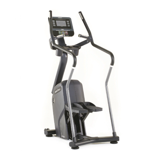
Table of Contents (Continued) 11.1 Specifications 11.2 Physical Dimensions (L x H x W) 11.3 Weight (kg/lbs) 11.4 Console Parts Lists & Exploded Diagrams 12.1 Parts Lists & Exploded Diagrams User Notes Assembly, Operation & Parts Manual G-Range... - Page 7 220G Overview 220G Step Handpulse Sensor Drinks Bottle Pedal Scuff Guard Console (Series 1, 2 or 3) Book Rest Resistance Adjustor Storage Bucket iPod / iPhone Dock ® ® Transport Wheels Levelling Foot Assembly, Operation & Parts Manual G-Range...
- Page 8 Contents of the 220G Pack The 220G Step will have to be assembled from the flat pack. The contents of the pack are as follows: Main Body Console (Series 1, 2 or 3) Book Holder Column iPhone / Pod Dock ®...
- Page 9 Assembly of the 220G 3.1 Connecting the Base Frame Insert Base Frame into the Main Body as indicated and then secure tightly with the base frame washers and bolts. Note: To aid installation undo the two cross-head screws on either side of the body. [See Figure A].
- Page 10 Assembly of the 220G (Continued) 3.2 Attaching the Scuff Guard Attach the Scuff Guard by placing over the frame joint and securing with 2 bolts.[See Figure B] Tools Required: Phillips Screwdriver Figure B Attaching the Scuff Guard Assembly, Operation & Parts Manual...
- Page 11 Assembly of the 220G (Continued) 3.3 Securing Pedals Figure C Securing Pedals Position Pedals so that the Pedal Shafts can pass through both plate and arm (ensure both shafts are well greased before assembly). Secure with washers and circlips. Then finally fix with grub screws, washers and lock nuts and cover with caps.
- Page 12 Assembly of the 220G (Continued) Figure D 3.4 Attaching the Pedals Attaching Pedals Place Pedal Mouldings onto the Metal Supporting Assemblies and secure both mouldings with the appropriate bolts. [See Figure D]. Note: Ensure that all bolts are tightened securely.
- Page 13 Assembly of the 220G (Continued) Figure E 3.5 Securing the Column Securing Column Rest the Column onto something stable e.g. a box or equivalent, and thread the Cable Loom up the through it, whilst making sure that the loom does not get trapped.
- Page 14 Assembly of the 220G (Continued) Figure F 3.6 Attaching Support Bars Attaching Support Bars Place the Support Bars into the Base Frame bosses and tighten with a screw. [See Figure F]. Tools Required: 3mm Allen Key [M6 x 6 Grub Screw] Assembly, Operation &...
- Page 15 Assembly of the 220G (Continued) Figure G 3.7 Attaching Handlebars Attaching Handlbars Secure the Handlebar onto the top of the Support Bars and attach the Handlebars to the Main Frame using the handlebar bolts, making sure that the Hand-Pulse sensor wire passes through the large hole and appears at the top of the frame.
- Page 16 Assembly of the 220G (Continued) Figure H 3.8 Fixing the iPod Dock/Storage Station ® ® Fixing the iPod Dock Place the iPod Dock Assembly onto the Bracket ® that’s attached to the Column and use a Phillips screwdriver to fasten 2x screws into the moulding, ensuring that the Dock is positioned straight before tightening screws*.
- Page 17 Installing Consoles on the 220G Figure J 4.1 Securing the Console Figure K Securing the Assembling the Place the bottom half of the Console onto the Console Console Column and secure with the Console Bolts. [See Figure J]. NOTE: Fasten Bolts securely.
- Page 18 Installing Consoles on the 220G (Continued) Figure L 4.3 Wiring the Console Wiring the Console Carefully pull the Electrical Connectors up from the Column. Ensure that all the Electrical Connectors attach to the Circuit Board as shown*. [See Figure Cables:...
- Page 19 Installing Consoles on the 220G (Continued) Figure M Assembling the Console 4.4 Assembling the Console Carefully lower the top Console Assembly into place and secure with the Console Screws*.[See Figure M]. Figure N NOTE: Fasten Screws securely. Securing the Book Holder Tools Required - 1 x Philips Head Screwdriver 4.5 Securing the Book Holder...
- Page 20 Installing Consoles on the 220G (Continued) Figure O 4.6 Using the Console Using the Console For details on how to use each of the Series 1, 2 & 3 Consoles, refer to documents: 135-1379-* Series 1 (Console 3.5 CV) 135-1299-* Series 2 (Console 5.0 CV) 135-1300-* Series 3 (Console 6.0 CV) Cirrus V1...
- Page 21 Alignment Checks on the 220G 5.1 Checking the alignment As a final check make sure that the Console, Handlebars, and Storage are correctly aligned and are not twisted. *Refer to document 135-767-* for further alignment instructions. Console Handlebars Storage Assembly, Operation & Parts Manual...
- Page 22 Fully Assembled 220G Step Your 220G-Step Stepper is now ready to use, please read the Technical and Console booklets to become familiar with all operational and safety features before use. Caution: MAKE SURE ALL HARDWARE IS TIGHT! Assembly, Operation & Parts Manual...
- Page 23 Do not stand or sit on plastic moulded covers. Never operate a PULSE FITNESS product if it has a damaged power cord or electrical plug, or if it has been dropped, damaged, or even partially immersed in water. Contact PULSE FITNESS' Global Service Team.
- Page 24 Do not use this product outdoors, near swimming pools or in areas of high humidity. Never operate a PULSE FITNESS product with the air openings blocked. Keep air openings free of lint, hair, or any other obstructing material.
- Page 25 If warnings are missing or damaged, please contact PULSE FITNESS immediately for replacement warning labels. Warning labels are shipped with every product and should be installed before product is used. PULSE FITNESS is not responsible for missing or damaged warning labels.
- Page 26 7.4 Battery Powered - Series 1 & 2 Only Series 1 & 2 consoles are powered by a rechargeable 12-volt battery. Mount the PULSE FITNESS Step (Independent Stepper) and begin stepping. The console should illuminate and programming a workout should be possible. The pedal action during workouts keeps the battery charged.
- Page 27 Important Safety Instructions (Continued) Figure P 7.5 Where to place the PULSE FITNESS Step Positioning (Independent Stepper) Following all safety instructions move the PULSE FITNESS Step (Independent Stepper) to the location in which it will be used. See Section 11, titled Specifications, for the dimensions of the footprint.
- Page 28 Consoles will show a message indicating it is initialising (which takes approximately 2 minutes). Note: If any of the Consoles do not light up, contact PULSE FITNESS' Global Service Team (refer to page 02 of this manual). Use only the power supply provided by PULSE FITNESS in order to ensure against unsafe operation.
- Page 29 8.1 Grounding Instructions This PULSE FITNESS product must be properly grounded. If the unit malfunctions or breaks down, proper grounding provides a path of least resistance for the electric current, which reduces the risk of shock to anyone touching or using the equipment. Each unit is equipped with an electrical cord, which includes an equipment grounding conductor and a grounding plug.
- Page 30 Installation 9.1 Location Select a suitable location for the PULSE FITNESS Step (Independent Stepper) before moving it. The site you choose should meet the following requirements: A flat, level and clean surface. Ÿ Close to a suitable power socket. Ÿ...
- Page 31 (Continued) Figure R 9.2 Feet Adjustment Feet Adjustment After placing the PULSE FITNESS Step (Independent Stepper) in position, check the unit’s stability by attempting to rock it. Any slight rocking indicates that the unit must be levelled. Check the front stabilising feet to determine which foot does not rest fully on the floor.
- Page 32 Installation (Continued) Figure S 9.3 On/Off Switch On / Off Switch The Independent Stepper is delivered with a separate power cable which has a moulded plug already tted and plug-in external power supply adaptor. Plug the cable out of the adaptor into the input socket at the front of the Independent Stepper, then plug the power cable into the adaptor and into a suitable mains socket and then switch on...
- Page 33 Cleaning & Maintenance 10.1 Preventive Maintenance Tips PULSE FITNESS products are backed by the engineering excellence and reliability of PULSE FITNESS and are one of the most rugged and trouble-free pieces of exercise equipment on the market today. Note: Safety can be maintained only if the equipment is examined regularly for damage or wear. Keep the equipment out of use until defective parts are repaired or replaced.
- Page 34 WARNING: Failure to carry out maintenance on the equipment as per this manual could result in serious injury and void your warranty. Please ensure all publications supplied with PULSE FITNESS equipment are read and understood. Assembly, Operation & Parts Manual...
- Page 35 10.6 Recycling the Battery When this PULSE FITNESS product is about to be discarded at the end of its useful life, the rechargeable battery must be removed and recycled. To access the battery, use a Phillips screwdriver to remove the cladding mouldings. To remove the battery, disconnect the cable, and remove the two screws holding the battery.
-
Page 36: Specifications
Specifications 11.1 - PULSE FITNESS Step (Independent Stepper) specifications: Designed use: Heavy/Commercial. Drive: Internal self tensioning poly V belt. Power: Generator brake. ‘Quick’ controls featuring handlebar resistance adjustments: Series 2 & 3. 40 Resistance levels: Series 1, 2 & 3. -
Page 37: Physical Dimensions (L X H X W)
Specifications (Continued) LAN (Ethernet or WiFi): Series 3 ONLY Integrated Television Tuner: Series 2 & 3 ONLY 11.2 Physical Dimensions (L x H x W) Length (cm/"): Series 1, 2 & 3 = 114cm / 44-7/8" Height (cm/"): Series 1 & 2 = 176cm / 69-5/16", Series 3 = 179cm / 70-1/2" Width (cm/"): Series 1, 2 &... - Page 38 Specifications (Continued) NTSC also supports PAL-M and PAL-N which are unique PAL encodings for Argentina, Brazil, Paraguay and Uruguay. PAL/SECAM tuner supports PAL, PAL-M, PAL-N, SECAM-B/G and SECAM-D/K. Workout Programmes: Series 1 - Quick Start, Goals (Time; Distance; Calories), Pacer (Time and speed; Time and distance; Speed and distance), Profile: X-country (easy, moderate, advanced), Aerobic (easy, moderate, advanced), Hill climb (easy, moderate, advanced), Intervals (easy, moderate, advanced), Random (easy, moderate, advanced), Heart rate control (variable heart rate training modes), Variable cool down with manual override.
- Page 39 Specifications (Continued) Series 2 - Profile display with level indicator, Track display with level indicator (pacer mode only), Time elapsed/remaining (depending on program), Distance elapsed/remaining (depending on program), SPM, Calories used, Watts, Heart rate, METs, User selectable/management programmable units (imperial/metric), User selectable/management programmable language.
-
Page 40: Parts Lists & Exploded Diagrams
12.1 Parts Lists & Exploded Diagrams - 220G Parts Lists & Exploded Diagrams Details on both Parts Lists & Exploded Diagrams for Series 2 & 3 220G Step (Independent Stepper), please refer to documents: 135-1087-02-* Exploded Dia. 135-1088-03-* Exploded Dia. (Short Version) 135-1093-01-* Series 2 (Console 5.0 CV) -
Page 41: User Notes
User Notes Assembly, Operation & Parts Manual G-Range... - Page 42 User Notes (Continued) Assembly, Operation & Parts Manual G-Range...
- Page 43 England, United Kingdom Tel: +44(0)1260 294600 Fax: +44(0)1260 299282 Email: global.service@pulsefitness.com © 2018 Pulse Fitness Ltd. All rights reserved. Pulse Fitness, is a registered trademark. Any use of these trademarks, without the express written consent of Pulse Fitness ® ® ®...
Need help?
Do you have a question about the 220G and is the answer not in the manual?
Questions and answers