Table of Contents
Advertisement
DR
®
SNOW BLOWER
`
SAFETY & OPERATING INSTRUCTIONS
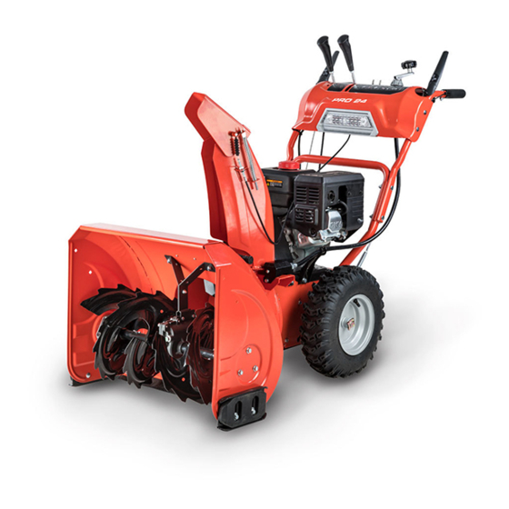
Models:
PRO-24
PRO-28
PRO XL-30
PRO MAX-34
Serial No.
Order No.
Read and understand this manual and all instructions before operating the DR SNOW BLOWER.
DR Power Equipment
Toll-free phone: 1-800-DR-OWNER (376-9637)
Fax: 1-802-877-1213
Website: www.DRpower.com
CONTACT US AT www.DRpower.com
1
Advertisement
Table of Contents


Need help?
Do you have a question about the PRO-24 and is the answer not in the manual?
Questions and answers