Advertisement
Quick Links
Advertisement

Related Manuals for Microbric Spiderbot


Summary of Contents for Microbric Spiderbot
- Page 1 Spiderbot Assembly Instructions Page 1...
- Page 2 1. Begin assembly by inserting one of the male/female extenders into a blue wheel. Then tie a piece of fishing line (or similar) around one of the spokes of the wheel. Then take the second blue wheel and fit it to the motor module. 2.
- Page 3 3. Assemble the “web” section of the spiderbot using a straight module and a right angle module with both positive (red) terminals on the inner edges. 4. Attach the “web” section of the spider bot to the Viper mainboard on p12. Use a 8mm spacer in the centre of the bric used to connect the web to the mainboard as this will be the point you attach one of the spiders cosmetic legs.
- Page 4 5. Construct the ‘tail’ section of the spiderbot as follows. Connect the bump sensor to the first right angle module using a normal screw in the centre and two male/female spacers on either side of the screw (as pictured). The space between the male female spacers will be used as a guide for the fishing line.
- Page 5 7. Place the fishing line between the two male/female spacers. 8. Place a bric onto the male/female spacers to close in the fishing line. You may need to adjust the male female spacers to align them with inserts of the bric. Page 5...
- Page 6 9. Construct the ‘fangs’ of the spider by connecting a bump module to the line tracker module. In this case you only need to use one screw and nut on each of the 3 brics pictured as the Linetracker is not “electronically’...
- Page 7 11. Setup two of the LED modules with 8mm spacers and vertically stacked brics. The wider board post of each bric should be on the same side top and bottom. 12. Connect the led ‘eye’ modules to p5 and p7. Page 7...
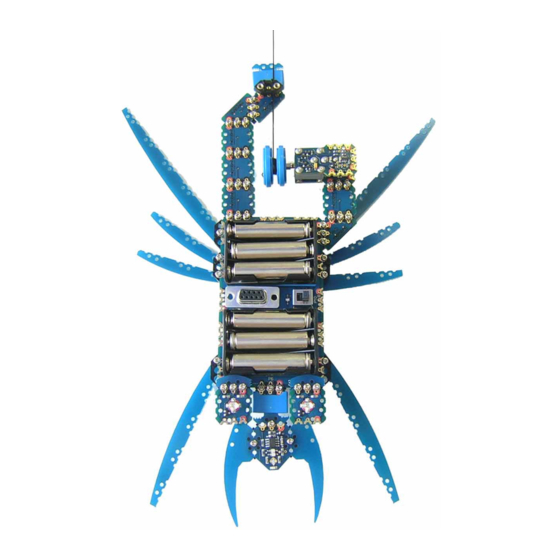
- Page 8 13. Complete the connection of the led modules by inserting screws into the connectors of p5 and p7. 14. Your spiderbot should now look like this. Page 8...
- Page 9 16. Connect the cosmetic legs to the viper. Notice the connection points of the legs. Now all that is required is loading the spiderbot.bas file (From the download section of www.microbric.com) into the Viper and your spiderbot will come to life!
Need help?
Do you have a question about the Spiderbot and is the answer not in the manual?
Questions and answers