
Related Manuals for P&B MPR3E5

Summary of Contents for P&B MPR3E5
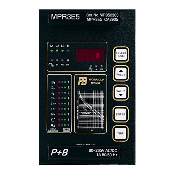
- Page 1 MPR 3E5 Digital Motor Protection Relay P&B Engineering Belle Vue Works Boundary Street Manchester M12 5NG Tel: 0161 230 6363 Issue H...
-
Page 2: Table Of Contents
Fax: 0161 230 6464 E-mail mail@pbeng.co.uk Contents ..................................ONTENTS 1. INTRODUCTION..............................2 2. APPLICATION................................3 3. FEATURES AND CHARACTERISTICS ....................... 3 4. DESIGN ..................................4 4.1 C ..............................4 IRCUIT IAGRAMS 4.1.1 Analogue input circuits........................... 5 4.1.2 Output relays..............................5 4.1.3Remote data communication.......................... - Page 3 ..............................24 NDIVIDUAL CASE 8.2 R ..............................24 ACK MOUNTING 8.3 T ............................24 ERMINAL CONNECTIONS 9. COMMISSIONING AND TESTING THE MPR3E5................... 24 9.1. C ..............................24 OMMISSIONING 9.2. T ................................25 ESTING 10. TECHNICAL DATA ............................. 28 10.1 M ..........................
-
Page 4: Introduction
1. Introduction The application of powerful microprocessors opens a new chapter for power system protective relaying. The digital processing of measured values and the ability to perform complex arithmetic and logic operations, give digital protection relays significant performance and flexibility improvements over their traditional analogue counterparts. -
Page 5: Application
2. Application The MPR 3E5 is a universal digital adjustable motor protection relay. It serves as overload, overcurrent, negative sequence (unbalance), and general protection for synchronous and induction machines. With a large selection of adjustment possibilities, the MPR 3E5 is suitable for almost any type of machine. -
Page 6: Design
4. Design 4.1 Circuit Diagrams Supply CASE CHASSIS POWER EARTH SUPPLY SPEED SWITCH TRIP SIGNAL ALARM Rstab PROGRAMMABLE RS485 CBCT MPR 3E5 Alternative E/F connection for CBT Typical Earthing Shown Fig 1 Connection Diagram for use with 3 line CT’s and alternative core balance CT. Supply CASE CHASSIS... -
Page 7: Analogue Input Circuits
4.1.1 Analogue input circuits The constantly monitored measuring values are galvanically decoupled, filtered and finally fed to the analogue/digital converter. The protection unit receives these analogue input signals of the phase currents I1, I2, I3 and Earth fault Ie, via separate input transformers. 4.1.2 Output relays The MPR 3E5 has three output relays, with single or dual pole change-over contacts as detailed in the previous diagram and summarised below:... -
Page 8: Front Panel
The measured and set values, and recorded fault data, are shown alphanumerically on the display. The meaning of the displayed values is easily interpreted from the LED indicators on the front panel. Because of the large adjustment possibilities the data on the MPR3E5 is split into a number of related groups Mode 1 Display. - Page 9 5.1.1. Mode 1 Display. The following subset of parameters are available for viewing and are accessed using the <SELECT/RESET> push-button in a cyclic manner. Pressing for longer than 1 second returns to the start of the cycle. Parameters available are either actual real-time running values or memorised values as follows: Data Displayed (ALL CURRENTS LED's Illuminated...
-
Page 10: Mode 2 Settings
5.1.2. Mode 2 Settings. The setting parameters may be changed in mode 2. Data Displayed LED No/ Colour t6x Setting 1/ Green Full Load Current I FLC 1/ Green - Flashing CT Primary Setting In 9/ Green - Flashing Hot / Cold Ratio 9/ Green Thermal O/L Pre-Alarm 1/ Green/Orange -Alternating... -
Page 11: Fault Indication
5.1.3. Fault indication When the relay has tripped, the display will show "TRIP" and the relevant LED will be illuminated red. On cycling through the displays in Mode 1, a four letter mnemonic describing the trip will be displayed. The mnemonics are listed in the table below. Trip Mnemonic Overload... -
Page 12: Working Principles
6. Working principles 6.1 Analogue circuits The incoming currents and voltages from the external transformers are converted to internal signals in proportion to the current and voltage, via the internal input transducers and shunt resistors. The noise signals caused by inductive and capacitive coupling are suppressed by an analogue RC filter circuit. -
Page 13: Operation And Setting
7. Operation and Setting 7.1 Layout of the control elements All control elements required for the operation and adjustment of the MPR 3E5 are located on the front panel. They are divided according to function into the three following groups: Alphanumeric Display: Indication of parameter set values, actual measured •... - Page 14 to mode (1) the user may press <TRIP>, followed by <SELECT/RESET> or alternatively wait for the automatic return which occurs after approximately 2 minutes of inactivity on the push buttons. The setting parameters may be changed in mode (2) using the procedure detailed above, the parameters are detailed in table 2: Data Displayed LED No/ Colour...
-
Page 15: Setting Procedure
7.3 Setting procedure In the following sections the setting of all relay parameters is described in detail: 7.3.1. t6x Setting This setting specifies the time the relay will take to trip at 6 times FLC, with respect to the cold characteristic curve, and therefore determines the basic thermal characteristic. -
Page 16: Hot/Cold Ratio Setting
Thermal Pre-Alarm level, the output alarm Relay will operate. 7.3.7. Number of Starts per Hour. The number of starts per hour the motor will make can be limited by the MPR3E5. The starting energy is integrated on a time-basis separately from the thermal overload model. This parameter can also be set to off in which case the number of starts is unlimited. -
Page 17: Earth Fault Trip Time
7.3.10. Earth Fault trip Time This setting determines the trip time following the measured earth fault current exceeding the pickup value. A setting of 0.0 indicates instantaneous operation, i.e. 30 - 50mS at twice times setting. 7.3.11. Unbalance Current This setting determines the pick-up level of the unbalance Current as a percentage of FLC before a Trip occurs. -
Page 18: Undercurrent Setting
7.3.12. Undercurrent Setting This setting determines the pickup upon an undercurrent, this is generally used to protect against an unloaded machine, e.g. Drive belt failure. A setting of OFF here will disable the feature. 7.3.13. Undercurrent Time This sets a time between the unit registering an undercurrent level and the actual tripping of the unit. 7.3.14. -
Page 19: Matrix Setting
7.4 Matrix Setting 7.4.1 Trip Relay Matrix, Tnnn This setting, range 000 to 255, sets the faults that are to operate the trip output relay. The setting also allows the Trip Relay to be either energised or de-energised upon activating. A Thermal Overload trip will always operate i.e. -
Page 20: Alarm Relay Matrix, Annn
7.4.3 Alarm Relay Matrix, Annn This setting range, 000 to 255, sets the faults that will cause the Alarm Relay to be either energised or de-energised upon activating. Example Only Thermal Pre-Alarm, Earth Fault Alarm and Low Set Alarm are required and the relay is to de- energise upon Alarm. -
Page 21: Trip/ Reset Matrix, Rnnn
DIP switch No1 on the 8 way internal switch-group selects the CT Secondary current of the Earth Fault input for a core balance application only i.e. when the matrix Ennn is set at E129 and above. See Section 4.13. For example, if the core balance CT Secondary is 1A and is used with a 5A Earth Fault rated relay, then the DIP Switch No 1 would be left at its normal setting of "OFF". -
Page 22: Speed Switch Matrix, Snnn
Action Numerical Value Value Enable Hot Restart 7.4.7 Speed switch Matrix, Snnn This setting, range 000 to 255, Enables/Disables the Speed Switch operation and selects the reduction in t6x time for a stalled motor. Example To configure the relay such that the Speed Switch is enabled with the effect of decreasing the t6x time by 75%, then the value set would be: 192 Action Numerical... - Page 23 Fault Inhibit This can be set to either enable or inhibit of all fault trips. Note that Thermal overload is always enabled irrespective of this fault inhibit setting. - Contactor Applications In order to avoid the possibility of a contactor attempting to break a short-circuit current in excess of its rating when this is the duty of the short circuit protective device e.g.
-
Page 24: Dip Switch Settings
7.5. DIP Switch Settings. An internal 10 way DIP switch is located behind the front panel. The factory pre-set values of this switch should not normally be changed. It can be accessed by withdrawing the relay from its case. Using a suitable tool (Medium Duty Hook/Spike -RS Stock No 549-533) the switches can be moved to carry out the following functions:- DIP switch Action... -
Page 25: Test Trip
7.6. Test Trip The whole tripping circuit of the protection system may be tested by simulating a fault with the <TRIP> push button. This button is also used to interrogate the relay for its software version number. In order to enter the test trip mode the user must be in display mode 2 (6.2.2). Upon pressing the <TRIP>... -
Page 26: Relay Case
The MPR 3E5 plug in module is supplied in a case which has a very compact plug and socket connector. The current terminals are equipped with self closing short circuit contacts. Thus the MPR 3E5 module can be unplugged even with current flowing without endangering personnel. 9. Commissioning And Testing The MPR3E5. 9.1. Commissioning. Auxiliary Power Supply The relay requires an auxiliary power supply connected to terminals 1 &... -
Page 27: Testing
For 5A secondary CT class 5P10 or 10P10 2.5VA (Allowing for up to 0.08Ω of secondary lead resistance) The CT primary rating must be not less than motor full load current and is usually selected as the next highest standard ratio. For Core Balance CT (CBCT) CT class 1.0/5P5, 2.5VA Note: higher standard VA ratings than suggested above may be chosen and this may allow higher... - Page 28 Relay Settings Test Current Nominal Operating Time THERMAL 1.0 x In 100.0 secs t6x = 10 = 0.5 x In 3.0 x In 10.0 secs LOW SET 4 x In 1 sec--** tI> =1.0 I> = 400% of FLC 6 x In 1 sec-** HIGH SET 8** x In...
- Page 29 MPR3E5, is between all the possible starting characteristics, and the full thermal withstand of the machine, for both hot & cold conditions.
-
Page 30: Technical Data
10. Technical Data 10.1 Measuring Input Circuits Rated Data Rated current, In 1A or 5A Rated frequency, fn 50Hz, 60Hz Power Consumption Current Circuits @ In = 1 A - 0.2 VA @ In = 5 A - 0.1 VA Thermal withstand Half wave 250 x In... -
Page 31: Tolerances
Measuring range of earth fault input is 0.4 x In. Current measuring errors ±1% of range. Thermal Current / Time Curves. The thermal curves shown overleaf are given by the following formula, used by the MPR3E5:- (Starting/Cold Condition) where 'p' is multiple of motor FLC (per unit value) 'a' is setting of t6x in seconds −... - Page 32 OVERLOAD PICKUP OF 1.05xFLC OVERLOAD PICKUP OF 1.10xFLC OPERATING CURVE 1 TIME CURVE 2 MULTIPLIER 'T' CURVE 3 CURVE 4 Multiples of FLC THERMAL CURRENT / TIME CURVES Relay Operating Time = t6x (seconds) x T Curve Type Hot/Cold Ratio Cold Curve Hot Curve Hot Curve...
-
Page 33: Output Contact Ratings
10 .6 Output contact ratings Number of relays Contacts = 2 change over contacts for trip signal. 1 change over contact for alarm & programmable. Maximum breaking capacity 250V AC / 1500VA / continuous current 6A for DC voltage: ohmic L/R = 4ms L/R = 7ms 300 V DC... -
Page 34: Housing
10.8 Housing Throughout the MR series range a modular housing system has been employed, utilising the latest high quality UK manufactured industry standard case components. This approach affords maximum flexibility for both the relay scheme designer and the maintenance engineer. The relay modules are fully Withdrawable for ease of maintenance and where applicable incorporate automatic short- circuiting CT connections to avoid dangerous open circuit CT overvoltages. -
Page 35: Connection Details
10.9 Connection Details The rear terminal block accepts both pre-insulated screw and push-on blade type connectors which may be used singly or in combination. Each terminal has 1 screw type and 2 blade type connectors. Screw: Each connection uses a 4mm (M4) screw outlet and accepts standard L-shaped ring type connectors designed for 4mm screws. -
Page 36: Order Form
11. Order Form QUANTITY MPR 3E5 Phase current Earth Phase current Aux Voltage 30V DC 80-265V AC/DC Housing 19" Rack Flush mounting PBSI Ltd Trading as P&B ENGINEERING Bell Vue Works, Boundary Street, Manchester. M12 5NG. Tel: 0161-230-6363 Fax: 0161-230-6464 17/12/97 Page 34 Issue H...
Need help?
Do you have a question about the MPR3E5 and is the answer not in the manual?
Questions and answers
what is price for mpr3E5